Chrysler Cirrus, Dodge Stratus, Plymouth Breeze Haynes. Manual - part 27


  Index      Manuals     Chrysler Cirrus, Dodge Stratus, Plymouth Breeze Haynes (1995-2000). Repair Manual


Search            


Content   ..  25  26  27  28   ..


Chrysler Cirrus, Dodge Stratus, Plymouth Breeze Haynes. Manual - part 27


9-4

Chapter 9 Brakes

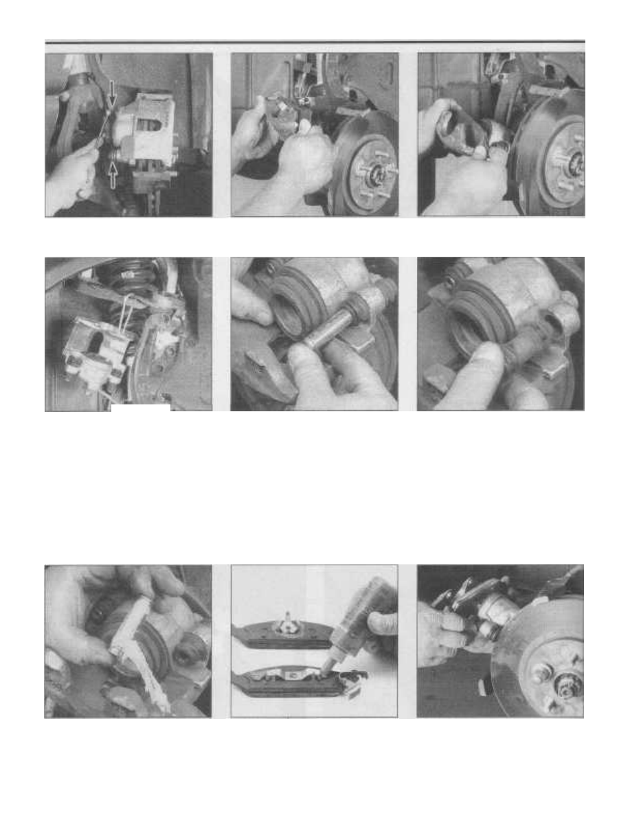
3.4a To remove the front brake caliper,

remove the two guide pin bolts (arrows)

3.4b Lift the caliper off the steering

knuckle and remove the outer

pad from the caliper

3.4c Remove the inner pad

from the caliper

3.4d If you're not going to reinstall the
caliper any time soon, hang it from the

upper control arm with a piece of wire

or equivalent - don't let it hang

by the brake hose

depressed to the bottom of the caliper bore,
the fluid in the master cylinder will rise as the

brake fluid is displaced. Make sure it doesn't

overflow. If necessary, siphon off more of the
fluid. Warning: Never siphon brake fluid by
mouth!
4

To replace the brake pads, follow

the accompanying photos, beginning with

illustration 3.4a. Be sure to stay in order and
read the caption under each illustration.
5

While the pads are removed, inspect the

caliper for brake fluid leaks and ruptures of

the piston dust boot. Replace the caliper if

necessary (see Section 4). Also inspect the
brake disc carefully (see Section 5). If
machining is necessary, follow the informa-

tion in that Section to remove the disc.

Inspect the brake hoses for damage and
replace if necessary (see Section 10).

3.4f Remove the bushing boots, inspect

them for damage and replace if necessary

6

Before installing the caliper guide pin

bolts, clean and check them for corrosion
and damage. If they're significantly corroded
or damaged, replace them. Be sure to tighten
the caliper guide pin bolts to the torque listed
in this Chapter's Specification Section.
7

Repeat the procedure for the opposite

wheel, then install the wheels, lug nuts and
lower the vehicle. Tighten the lug nuts to the
torque listed in the Chapter 1 Specification
Section. Add the appropriate brake fluid to

3.4e Remove the guide pin bushings

3.4g Lubricate the guide pin bushings

with multi-purpose grease before

installing them

3.4h Apply an anti-squeal compound to

the backs of the pads where they mate

with the caliper and piston

3.4i Install the inner brake pad - make

sure the retaining spring is fully

seated into the piston bore

Chapter

9

Brakes

9-5

3.4j Install the outer brake pad - make sure

the retaining spring is properly engaged

with the caliper body and the wear

indicator (arrow) on the pad is positioned

at the top of the caliper as shown

the reservoir until it's full (see Chapter 1 if

necessary).

8

Pump the brakes several times to seat

the pads against the disc, then check the

brake fluid level in the reservoir again. Top it
up as necessary.

9

Carefully test the operation of the

brakes before resuming normal operation.

Try to avoid heavy brake applications until
the brakes have been applied lightly several
ti mes to seat the pads.

4

Disc brake caliper - removal and
installation

Warning: Dust created by the brake system
may contain asbestos, which is harmful to
your health. Never blow it out with com-
pressed air and don't inhale any of it. An
approved filtering 
mask should be worn when

working on the brakes. Do not, under any cir-
cumstances, use petroleum-based solvents
to clean brake parts. Use brake system
cleaner only.
Note: If replacement is indicated (usually
because of fluid 
leaks, a stuck piston or bro-
ken bleed screw) explore all options 
before
beginning this procedure. New and factory
rebuilt calipers are available on an exchange
basis, which makes this job quite easy.

Always replace the calipers in pairs - never

replace just one of them.

Removal

1

Loosen the front wheel lug nuts, raise

the vehicle and support it securely on jack-
stands. Remove the front wheels.
2

Unscrew the banjo bolt from the caliper

and detach the hose. Note: If you're just
removing the caliper for 
access to other com-
ponents, don't disconnect the 
hose. Discard
the sealing washers on each side of the fitting
and use new ones during installation. Plug the
hose to prevent fluid loss and contamination.
3

Refer to the first few steps in Section 3

(caliper removal is the first part of the brake

3.4k Place the caliper/brake pad

assembly onto the steering knuckle

(make sure the upper ends of

the pads seat properly)

pad replacement procedure). Clean the
caliper assembly with brake system cleaner.
Warning: DO NOT, under any circumstances,
use kerosene, gasoline or petroleum-based

solvents to clean brake parts! Be sure to

check the pads as well and replace them if
necessary (see Section 3).

Installation
4

Install the brake pads and caliper (see

Section 3). Tighten the caliper guide pin bolts
to the torque listed in this Chapter's Specifi-
cation Section.
5

Connect the brake hose to the caliper

using new sealing washers. Tighten the banjo
bolt to the torque listed in this Chapter's
Specification Section.
6

Firmly depress the brake pedal a few

times to bring the pads into contact with the
disc. Check the fluid level in the master cylin-
der reservoir and add more if necessary.
7

Bleed the brakes (see Section 11).

8

Install the wheels and lug nuts. Lower

the vehicle and tighten the lug nuts to the
torque listed in the Chapter 1 Specifications.
9

Carefully check for fluid leaks and test

the operation of the brakes before resuming
normal operation.

5.2 The brake pads on this vehicle were
obviously neglected, as they wore down
to the rivets, then cut deep grooves into

the disc, which must now be replaced

3.41 Install the guide pin bolts and tighten

them to the torque listed in this

Chapter's Specifications

5

Brake disc - inspection, removal

and installation

Inspection

Refer to illustrations 5.2, 5.3, 5.4a and 5.4b

1

Loosen the wheel lug nuts 1/4-turn,

raise the front of the vehicle and support it
securely on jackstands. Apply the parking

brake. Remove the front wheels. Reinstall the
lug nuts to hold the disc firmly against the
hub. Note: Washers may be required.

2

Remove the brake caliper (see Sec-

tion 4). Visually inspect the disc surface for
score marks and other damage (see illustra-
tion). 
Light scratches and shallow grooves
are normal after use and won't affect brake
operation. Deep grooves - over 0.015-inch
deep - require disc removal and refinishing

by an automotive machine shop. Be sure to

check both sides of the disc.
3

To check the disc runout, place a dial

indicator at a point about 1/2-inch from the
outer edge of the disc (see illustration).
Rotate the disc until you find the lowest point
on the disc. Set the dial indicator to zero and

turn the disc again. The indicator reading

should not exceed the runout limit listed in

this Chapter's Specification Section. Check

5.3 Use a dial indicator to check disc

runout - if the reading exceeds the

specified runout limit, the disc will

have to be machined or replaced

9-6

Chapter

9

Brakes

the runout on both sides of the disc. If the
runout exceeds specification, the disc must
be refinished by an automotive machine
shop. Note: Professionals recommend resur-
facing the brake discs regardless of the dial
indicator reading (to produce a smooth, flat
surface that will eliminate brake pedal pulsa-
tions and other undesirable symptoms related
to questionable discs). At the very 
least, if you
elect not to have the discs resurfaced,
deglaze them with sandpaper 
or emery cloth.
4

The disc must not be machined to a

thickness less than the specified minimum
thickness. The minimum (or discard) thick-
ness is cast into the disc (see illustration).
The disc thickness should be checked with a
micrometer (see illustration).

Removal

Refer to illustration 5.7
5

Loosen the wheel lug nuts 1/4-turn,

raise the vehicle and place it securely on
jackstands. Remove the wheel.
6

Remove the caliper (see Section 4).

7

Remove the retaining clips, if present,

from the wheel studs (see illustration).
8

Pull the disc off the hub.

Installation
9

Installation is the reverse of removal.

Make sure you tighten the caliper guide pin
bolts to the torque listed in this Chapter's
Specification Section. Tighten the lug nuts to
the torque listed in the Chapter 1 Specifica-
tions.

6

Drum brake shoes - replacement

Refer to illustrations 6.2, 6.4a through 6.4v
and 
6.5
Warning: Drum brake shoes must be
replaced on both wheels at the 
same time -
never replace the 
shoes on only one wheel.

Also, the dust created by the brake system

may contain asbestos, which is harmful to

your health. Never blow it out with com-
pressed air and don't inhale any of it. An

5.4a The minimum thickness is cast into

the inside of the disc

approved filtering mask should be worn when
working on the 
brakes. Do not, under any cir-
cumstances, use petroleum-based solvents
to clean brake parts. Use brake system
cleaner only!
Caution: Whenever the brake shoes are
replaced, the hold-down springs should also
be replaced.

Due to the continuous

heating/cooling cycle that the springs are
subjected to, they lose their tension over a
period of time and may allow the 
shoes to
drag on the drum and wear at a much faster
rate than normal.
1

Loosen the wheel lug nuts 1/4-turn,

raise the rear of the vehicle and support it
securely on jackstands. Block the front
wheels to keep the vehicle from rolling.
Release the parking brake. Remove the
wheel. Note: The brake shoes on both wheels
must be replaced at 
the same time. The drum
brake 
assemblies on these models are unique
for each side of the vehicle (left hand only -
right hand only) so to avoid mixing up parts,
service one brake assembly at a time.
2

Remove the brake drum. If the drum

won't come off, the brake shoes must be
retracted from their fully adjusted position by
inserting a screwdriver through the adjuster
hole in the backing plate. Locate the adjuster

5.4b Use a micrometer to measure the

thickness of the disc at several locations

5.7 Cut off and discard the disc retaining

washers, if present (it isn't necessary

to reinstall them)

access hole and remove the plug. Insert a

screwdriver through the access hole and

engage the adjuster quadrant teeth. Using

the screwdriver, move the adjuster quadrant
teeth fully toward the FRONT of the vehicle.
The drum should now come off. Wash the

brake assembly with brake system cleaner
(see illustration).

6.2 Before disassembling the brake shoe assembly, spray it with

brake cleaner to remove brake dust; DO NOT blow brake

dust off with compressed air

6.4a Using locking pliers, grasp the lower return spring and

detach it from the leading brake shoe (left hand

brake assembly shown

Chapter 9 Brakes

9-7

6.4b Remove the lower return spring -

note that the shorter spring end is

towards the trailing brake shoe

6.4c Using locking pliers, grasp the upper

return spring and detach it from the

trailing brake shoe

6.4d Unhook the upper return spring from

the leading brake shoe

6.4e Using locking pliers, detach the

automatic self-adjuster spring

from the adjuster

3

Remove the wheel hub/bearing assembly

(see Chapter 10). Note: Removal of the wheel

hub/bearing assembly is not mandatory, but it
makes the job a lot easier.
4

Follow illustrations 6.4a through 6.4v

for inspection and replacement of the brake

6.4f Compress the retaining clip,

remove the pin .. .

shoes. Be sure to stay in order and read the
caption under each illustration.
5

Before reinstalling the drum, carefully

examine it for cracks, score marks, deep
scratches and hard spots, which will appear
as small discolored areas. If the hard spots

6.4g . . . and separate the leading brake

shoe and the automatic self-adjuster

from the backing plate

cannot be removed with fine emery cloth or if
any of the other conditions listed above exist,
the drum must be taken to an automotive
machine shop to have it resurfaced. Note:
Professionals recommend resurfacing the
drums whenever a brake job is performed.

6.4h To remove the adjuster from the shoe, pull it outward, then

rotate it toward the reinforced side of the shoe

6.4i Compress the retaining clip, then remove the pin

and clip from the trailing shoe

LEADING BRAKE

SHOE ASSEMBLY

FULLY EXTEND ADJUSTER

IN THIS DIRECTION ROTATE

THIS

DIRECTION

AUTOMATIC SELF

ADJUSTER MECHANISM

9-8

Chapter 9 Brakes

6.4j Detach the parking brake cable from

the actuating lever - DO NOT try to

separate the actuating lever

from the brake shoe

6.4m Correctly position the trailing shoe

in place on the backing plate (parking

brake actuating lever toward the

inside) and secure it with a new

pin and retaining clip

Resurfacing will eliminate the possibility of
out-of-round drums. If the drums are worn so
much that they can't be resurfaced without
exceeding the maximum allowable diameter

6.4k Before installing the brake shoes,

apply a small amount of high-temperature
grease to all areas where the brake shoes

make contact with the backing plate

(stamped into the drum) (see illustration),
then new ones will be required. At the very

least, if you elect not to have the drums resur-

faced, remove the glazing from the surface
with emery cloth or sandpaper using a

swirling motion.

6

Install the wheel hub/bearing assembly

6.41 Obtain the correct replacement

trailing brake shoe (they are unique for

each side of the vehicle, RH or LH and the

parking brake actuating lever should be

permanently attached) and install the

parking brake cable onto the

actuating lever

6.4n Inspect the automatic self-

adjuster for damage and replace if

necessary

1

Knurled pin - check to see it is
firmly attached and the teeth are
not damaged or excessively worn

2

Quadrant spring - inspect for
damage and verify it hasn't lost
it's tension

3

Quadrant - verify the quadrant is
free to slide within its mounting
slot and can rotate through the
entire tooth range

(with a new hub nut), if removed (see Chap-
ter 10).
7

Install the brake drum, mount the wheel

and install the lug nuts.
8

Repeat the procedure for the opposite

wheel.
9

Lower the vehicle and tighten the lug

LUBRICATE THIS

SURFACE BETWEEN

AUTOMATIC SELF

QUADRANT AND STRUT

KNURLED

ADJUSTER MECHANISM

OF ADJUSTER MECHANISM

PIN

STRUT

QUADRANT

SPRING

6.4o Before installing the adjuster on the leading brake shoe,

lubricate the area between the quadrant and the adjuster

strut with a small amount of multi-purpose grease

6.4p Install the automatic self-adjuster onto the proper leading

brake shoe (they are unique for each side of the vehicle, RH or LH
and are marked on the reinforcement plate) - after installation the

quadrant teeth should be on the reinforced side of the brake shoe

Chapter 9 Brakes

9-9

6.4q Place the leading brake shoe (with

adjuster installed) in position on the

backing plate, making sure to match up

the notch in the adjuster strut with the

notch in the trailing brake shoe

nuts to the torque listed in the Chapter 1
Specifications.
10

To adjust the brakes, start the engine

and fully depress the brake pedal two or

three times to activate the automatic

adjusters.
11

Carefully test brake operation before

driving the vehicle in traffic.

7

Wheel cylinder - removal and

installation

Note: If replacement is warranted (usually
because of fluid leakage or sticky operation)
explore all options before beginning the job.
New wheel cylinders are available, which
makes this job quite easy. Never replace only
one wheel cylinder. Always replace both of
them at the 
same time.

Removal

Refer to illustration 7.2
1

Remove the rear brake shoes (see Sec-

tion 6).
2

Using a flare-nut wrench (if available)

disconnect the brake line fitting from the rear

6.4r Install the new pin and retaining clip

6.4t Install the adjuster spring into the

trailing brake shoe, then attach

it to the adjuster

of the wheel cylinder (see illustration). Plug
the end of the brake line to prevent fluid loss
and contamination.
3

Remove the two bolts securing the

wheel cylinder to the backing plate and
remove the wheel cylinder.

Installation

4

Installation is the reverse of removal.

6.4s Compress the retaining clip

and turn the pin 90-degrees to

retain the brake shoe

Tighten the wheel cylinder mounting bolts to
the torque listed in this Chapter's Specifica-
tions. Tighten the line fitting securely.
5

Install the brake shoes, wheel hub/bear-

ing assembly, if removed (with a new hub nut)

and brake drum (see Section 6).
6

Bleed the brakes (see Section 11). Care-

fully test brake operation before resuming
normal operation.

6.4u Install the upper return spring

6.4v Install the lower return spring,

positioned as shown

6.5 The maximum allowable diameter is

stamped into the drum (arrow)

7.2 Disconnecting the brake hose fitting

(arrow) from the wheel cylinder

9-10

Chapter 9 Brakes

8.2 Cruise control servo mounting

nuts (arrows)

8

Master cylinder - removal,
installation and fluid reservoir
replacement

Note: The master cylinder used on these
vehicles is not serviceable and must be
replaced as a unit. However, you can replace
the fluid reservoir and/or reservoir sealing

grommets.

Removal

Refer to illustrations 8.2, 8.5, 8.6 and 8.8
1

Disconnect the negative battery cable

from the ground stud on the left shock tower
(see Chapter 5, Section 1). With the ignition
switch in the OFF position, pump the brake
pedal until a firm pedal is achieved.
2

If equipped, disconnect the cruise con-

trol electrical connector and detach the
cruise control servo from its mounting on the
shock tower and position it out of the way
(see illustration).
3

Using a syringe or equivalent, siphon the

brake fluid from the master cylinder reservoir
and dispose of it properly. Caution: Brake
fluid will damage paint. Cover all painted sur-
faces and avoid spilling fluid during this pro-
cedure.
4

Place rags under the brake line fittings

and prepare caps or plastic bags to cover the
ends of the lines once they're disconnected.
5

Loosen the tube nuts at the ends of the

brake lines where they enter the master cylin-
der (see illustration). To prevent rounding off

the corners of these fittings, a flare-nut
wrench, which wraps around the nut, should

be used. Pull the brake lines away from the
master cylinder slightly and plug the ends to
prevent leakage and contamination. Also
plug the openings in the master cylinder to
prevent fluid spillage.
6

Unhook the clip and unplug the electri-

cal connector from the brake fluid level sen-
sor (see illustration).

7

Clean the area where the master cylin-

der attaches to the vacuum booster using

brake system cleaner.

8

Remove the two master cylinder mount-

ing nuts (see illustration) and any brackets

that may be attached. Slide the master

8.5 Disconnect the brake line fittings with

a flare-nut wrench (ABS-equipped

models have two line fittings, while

non-ABS models have four)

cylinder off the studs and remove it from the
vehicle.

Installation

Note: Read this entire procedure before
beginning this operation.
9

Install the master cylinder onto the

power brake booster making sure to engage
the operating rod. Install any brackets as
necessary and tighten the mounting nuts
securely.
10

Before installing the brake lines to the

master cylinder, it should be bled. Since
you'll have to apply pressure to the master
cylinder piston and at the same time, control
flow from the brake line outlets, the aid of an
assistant will be required.
11

Insert threaded plugs into the brake line

outlet holes and snug them down so no air
will leak past them, but not so tight that they
can't be easily loosened.
12

Fill the reservoir with the recommended

brake fluid (see Chapter 1).
13

Place a suitable container under one of

the plugs and remove the plug. Have your
assistant SLOWLY depress the brake pedal
to expel the air from the master cylinder. Use
a rag to catch any brake fluid that squirts out.

A clear plastic bag placed over the master

cylinder will help you guide the expelled fluid
for collection and prevent it from squirting in
unwanted areas.
14

To prevent air from being drawn back

into the master cylinder, place your finger

tightly over the hole to keep air from being

drawn back into the master cylinder before
releasing the brake pedal. Wait several sec-
onds for brake fluid to be drawn from the
reservoir into the bore, then depress the
brake pedal again, removing your finger as
brake fluid is expelled. Be sure to put your

finger firmly back over the hole each time

before releasing the piston, and when the
bleeding procedure is complete for that out-
let, install the plug (with the pedal depressed)
and tighten it before going on to the next
port.
15

Repeat the procedure until only brake

fluid is expelled from the brake line outlet

8.6 Unhook the retaining clip and unplug

the electrical connector from the brake

fluid level sensor

hole. When only brake fluid is

'

expelled,

repeat the procedure at the other outlets. Be
sure to keep the master cylinder reservoir

filled with brake fluid to prevent the introduc-
tion of air into the system.

16

Loosen the master cylinder mounting

nuts and connect the brake lines into the
master cylinder. Since the master cylinder is
a bit loose, it can be moved slightly so the fit-

tings can thread in easily.

17

Tighten the master cylinder mounting

nuts to the torque given in this Chapter's
Specification Section. Tighten the fitting nuts

securely.

18 If equipped, install the cruise control

servo onto the shock tower and plug in the
electrical connector.

19

Fill the master cylinder reservoir with the

recommended fluid (see Chapter 1), then
bleed the brake hydraulic system (see Sec-

tion 11).

Fluid reservoir

replacement

Refer to illustration 8.22
20

Using a syringe or equivalent, siphon the

brake fluid from the master cylinder reservoir
and dispose of it properly.

8.8 To detach the master cylinder from

the power brake booster, remove the

mounting nuts (arrows), then pull the

master cylinder assembly straight

off the mounting studs

Chapter 9 Brakes

9-11

8.22 The brake fluid reservoir is secured and sealed

to the master cylinder by the grommets

9.5 On non-ABS models, the proportioning valves are located on

the right side of the front suspension crossmember

21

Disconnect the brake fluid level sensor

electrical connector from the reservoir (see
illustration 8.6).
22

To remove the reservoir, carefully rock it

back-and-forth while gently pulling upward
(see illustration).
23

After removing the reservoir, carefully

remove the grommets from the master cylin-
der. Note: New grommets should be installed

anytime the reservoir is detached from the
master cylinder.
24

Remove the brake fluid level sensor

from the reservoir.
25 Installation is the reverse of removal.
Coat the new grommets with clean brake
fluid prior to installation.

9

Proportioning valves - check and
replacement

Description

1

All models have two proportioning

valves that balance front-to-rear braking by
controlling the increase in rear system
hydraulic pressure above a preset level.
Under light pedal pressure, the valve allows

full hydraulic pressure to the front and rear

brakes. But above a certain pressure - known
as the "split point" - the proportioning valve
reduces the amount of pressure increase to

the rear brakes in accordance with a prede-
termined ratio. This lessens the chance of
rear wheel lock-up and skidding.

Check

2

If either rear wheel skids prematurely

under hard braking, it could indicate a defec-
tive proportioning valve. If this occurs, have
the system checked out by your local dealer
service department. A pair of special pres-
sure gauges and fittings are required for
proper diagnosis of the proportioning valves.
While diagnosis is beyond the scope of the
home mechanic, you may still save money by
replacing the valves yourself.

Replacement

Non-ABS models

Refer to illustration 9.5
3

Loosen the right front wheel lug nuts,

raise the front of the vehicle and support it
securely on jackstands. Remove the wheel.
4

Remove the accessory drivebelt splash

shield (see Chapter 1).
5

Loosen the brake hydraulic fluid lines

from the proportioning valve with a flare-nut
wrench to prevent rounding off the corners of
the fittings (see illustration). Back off the fit-
tings and remove the valve from the line. Plug
the ends of the lines to prevent loss of brake

fluid and the entry of dirt.

6

Installation is the reverse of removal.

7

Bleed the brakes (see Section 11). Care-

fully test the brakes before resuming normal

operation.

1995 to 1997 models with ABS

Refer to illustration 9.8
8

If your vehicle was manufactured

between 1995 and 1997 and equipped with

ABS, the proportioning valves are mounted
to the HCU (see illustration) and upon
removal, the ABS system will be required to
be bled using a DRB scan tool. We recom-
mend you let your local dealer service
department or other qualified repair shop
replace the proportioning valves on these
models.

1998 and later models with ABS

Refer to illustration 9.10
9

Loosen the appropriate rear wheel lug

nuts, raise the rear of the vehicle and support
it securely on jackstands. Remove the wheel.
10

Loosen the line fitting from the propor-

tioning valve with a flare-nut wrench to pre-
vent rounding off the corners of the fittings
(see illustration). Be sure to hold the valve
with another wrench to prevent the line from
twisting.
11

Detach the brake hose bracket from the

upper frame rail.
12

Unscrew the valve from the brake hose

and plug the ends of the lines to prevent
leakage and contamination.

9.8 On 1995 to 1997 models equipped

with ABS, the proportioning valves

(arrows) are threaded into the Hydraulic

Control Unit which is mounted on the right
side of the front suspension crossmember

9.10 On 1998 and later models equipped

with ABS, the proportioning valves are

located in the rear wheel well and

mounted on the upper frame rail between

the metal brake line and the brake hose

9


Content   ..  25  26  27  28   ..