содержание .. 7 8 9 10 ..
Peugeot 405. Manual - part 9
6 It is advisable to remove the dirt from the
spark plug recesses, using a clean brush,
vacuum cleaner or compressed air before
removing the plugs, to prevent dirt dropping
into the cylinders.
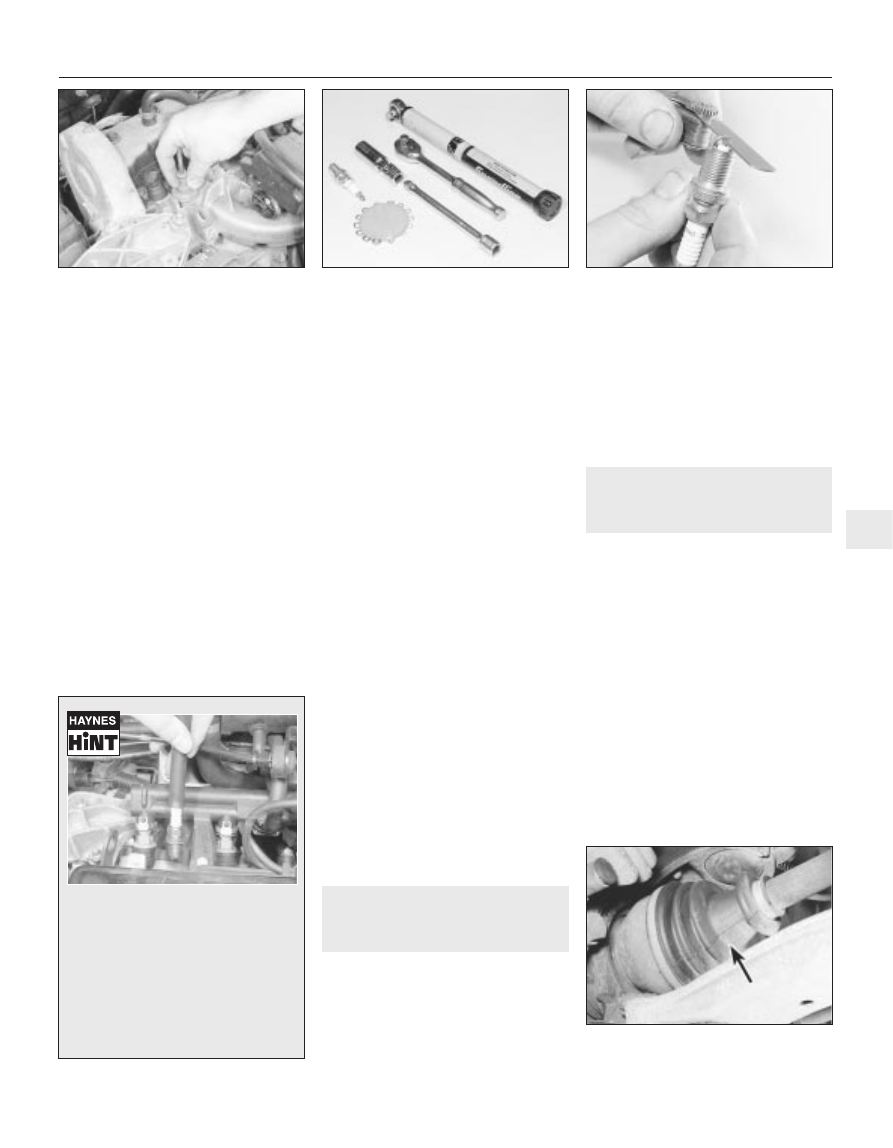
7 Unscrew the plugs using a spark plug
spanner, suitable box spanner, or a deep
socket and extension bar (see illustration).
Keep the socket aligned with the spark plug -
if it is forcibly moved to one side, the ceramic
insulator may be broken off. As each plug is
removed, examine it as follows.
8 Examination of the spark plugs will give a
good indication of the condition of the engine.
If the insulator nose of the spark plug is clean
and white, with no deposits, this is indicative
of a weak mixture or too hot a plug (a hot plug
transfers heat away from the electrode slowly,
a cold plug transfers heat away quickly).
9 If the tip and insulator nose are covered
with hard black-looking deposits, then this is
indicative that the mixture is too rich. Should
the plug be black and oily, then it is likely that
the engine is fairly worn, as well as the mixture
being too rich.
10 If the insulator nose is covered with light
tan to greyish-brown deposits, then the
mixture is correct, and it is likely that the
engine is in good condition.
11 The spark plug electrode gap is of
considerable importance as, if it is too large or
too small, the size of the spark and its
efficiency will be seriously impaired. The gap
should be set to the value given in the Specifi-
cations at the beginning of this Chapter.
12 To set the gap, measure it with a feeler
blade, then bend the outer plug electrode until
the correct gap is achieved (see illustration).
The centre electrode should never be bent, as
this may crack the insulator and cause plug
failure, if nothing worse. If using feeler blades,
the gap is correct when the appropriate-size
blade is a firm, sliding fit.
13 Special spark plug electrode gap
adjusting tools are available from most motor
accessory shops, or from some spark plug
manufacturers.
14 Before fitting the spark plugs, check that
the threaded connector sleeves (on top of the
plug) are tight, and that the plug exterior
surfaces and threads are clean. It is very often
difficult to insert spark plugs into their holes
without cross-threading them. To avoid this
possibility, fit a short length of hose over the
end of the spark plug (see Haynes Hint).
15 Remove the rubber hose (if used), and
tighten the plug to the specified torque (see
“Specifications”) using the spark plug socket
and a torque wrench. Refit the remaining
plugs in the same way.
16 Connect the HT leads in the correct order,
and refit any components removed for
access. On 1998 cc 16-valve models, connect
the HT coils in their correct order.
12 Clutch adjustment check
and control mechanism
lubrication
2
Note: On models from 1994, the maker’s
specified interval for this procedure is
9000 miles (15 000 km) or 12 months for clutch
adjustment, and 18 000 miles (30 000 km) for
lubrication.
1 Check that the clutch pedal moves
smoothly and easily through its full travel.
2 The clutch itself should function correctly,
with no trace of slip or drag.
3 Where possible, adjust the clutch cable if
necessary, as described in Chapter 6.
4 If excessive effort is required to operate the
clutch, check first that the cable is correctly
routed and undamaged. Remove the pedal,
and make sure that its pivot is properly
greased. Refer to Chapter 6 for further
information.
13 Driveshaft gaiter check
1
Note: On models from 1994, the maker’s
specified interval for this procedure is
9000 miles (15 000 km) or 12 months.
With the vehicle raised and securely
supported on stands, turn the steering onto
full lock, then slowly rotate the roadwheel.
Inspect the condition of the outer constant
velocity (CV) joint rubber gaiters, while
squeezing the gaiters to open out the folds
(see illustration). Check for signs of cracking,
splits, or deterioration of the rubber, which
may allow the grease to escape, and lead to
water and grit entry into the joint. Also check
the security and condition of the retaining
clips. Repeat these checks on the inner CV
joints. If any damage or deterioration is found,
the gaiters should be renewed without delay
as described in Chapter 8.
At the same time, check the general
condition of the CV joints themselves, by first
holding the driveshaft and attempting to rotate
12 000 Mile / 12 Month Service
1•15
13.1 Check the condition of the driveshaft
gaiters (arrowed)
11.12 Measuring the spark plug gap with a
feeler blade
11.7 Tools required for spark plug
removal, gap adjustment and refitting
11.5 Pulling the HT leads
from the spark plugs
1
It is often difficult to insert spark plugs
into their holes without cross-threading
them. To avoid this possibility, fit a
short length of 5/16 inch internal
diameter rubber hose over the end of
the spark plug. The flexible hose acts as
a universal joint to help align the plug
with the plug hole. Should the plug
begin to cross-thread, the hose will slip
on the spark plug, preventing thread
damage to the cylinder head.