содержание .. 6 7 8 9 ..
Peugeot 405. Manual - part 8
Allen key through the special hole and
tightening the peg.
27 Unscrew the mounting bolts and remove
the tensioner roller, then slip the auxiliary
drivebelt from the pulleys.
28 Check that the tensioner pulleys turn
freely without any sign of roughness.
Refitting and tensioning
29 If the belt is being renewed, ensure that
the correct type is used. Fit the belt around
the pulleys making sure that it is engaged with
the correct grooves in the pulleys.
30 Refit the tensioner roller and tighten the
mounting bolts.
31 Using the square drive key hold the
automatic adjuster, then release the peg and
slowly allow the tensioner to tighten the belt.
Check again that the belt is correctly located
in the pulley grooves.
32 Reconnect the battery negative lead.
33 Refit the engine undercover and
wheelarch cover. Refit the roadwheel, and
lower the vehicle to the ground.
Power steering pump drivebelt
(XU9J4 16-valve) models
Removal
34 Drain the hydraulic fluid from the system
as described in Chapter 10.
35 Loosen the pump mounting bolts and
remove the drivebelt.
36 Disconnect the high and low pressure
unions on the pump.
37 Remove the bolts and lift off the pump.
Refitting and tensioning
38 Refit in reverse order, then tension the
belt by applying a torque of 55 Nm for a new
belt and 30 Nm for a used belt by using the
square of a torque wrench in the square cut-
out in the pump bracket, tightening the
mounting bolts while the torque tension is
maintained (see illustration).
39 Fill and bleed the system (see Chapter 10).
6
Hose and fluid leak check
1
Note: On models from 1994, the maker’s
specified interval for this procedure is
9000 miles (15 000 km) or 12 months.
1 Visually inspect the engine joint faces,
gaskets and seals for any signs of water, oil or
fuel leaks. Pay particular attention to the areas
around the camshaft cover, cylinder head, oil
filter and sump joint faces. Bear in mind that,
over a period of time, some slight seepage
from these areas is to be expected. What you
are really looking for is any indication of a
serious leak. Should a leak be found, renew
the offending gasket or oil seal by referring to
the appropriate Chapters in this manual.
2 Also check the security and condition of all
the engine-related pipes and hoses. Ensure
that all cable-ties or securing clips are in place
and in good condition. Clips which are broken
or missing can lead to chafing of the hoses,
pipes, or wiring, which could cause more
serious problems in the future.
3 Carefully check the radiator hoses and
heater hoses along their entire length. Renew
any hose which is cracked, swollen, or
deteriorated. Cracks will show up better if the
hose is squeezed. Pay close attention to the
hose clips that secure the hoses to the
cooling system components. Hose clips can
pinch and puncture hoses, resulting in cooling
system leaks. If the original Peugeot crimped-
type hose clips are used, it may be a good
idea to replace them with standard worm-
drive hose clips.
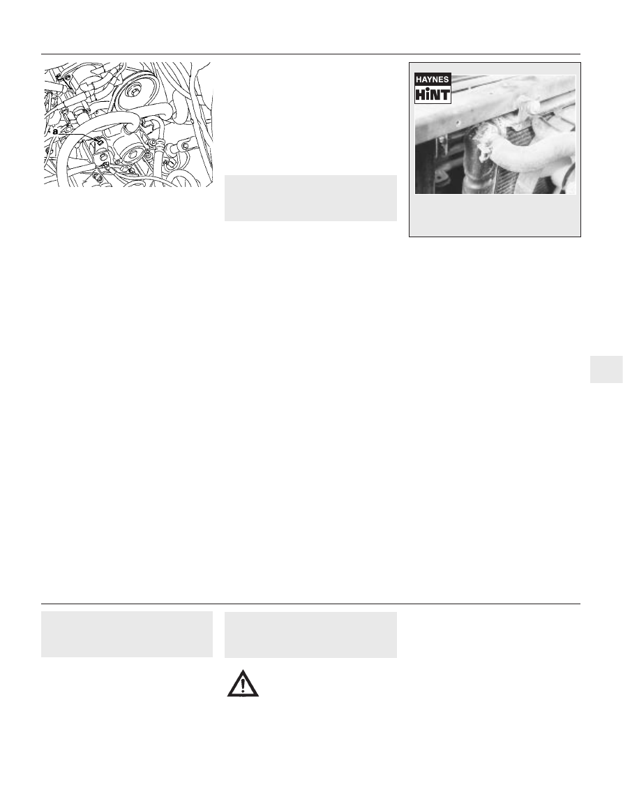
4 Inspect the cooling system (hoses, joint
faces, etc.) for leaks (see Haynes Hint).
5 Where any problems of this nature are
found on system components, renew the
component or gasket, referring to Chapter 3.
6 Where applicable, inspect the automatic
transmission fluid cooler hoses for leaks or
deterioration.
7 With the vehicle raised, inspect the petrol
tank and filler neck for punctures, cracks, and
other damage. The connection between the
filler neck and tank is especially critical.
Sometimes, a rubber filler neck or connecting
hose will leak due to loose retaining clamps or
deteriorated rubber.
8 Carefully check all rubber hoses and metal
fuel lines leading away from the petrol tank.
Check for loose connections, deteriorated
hoses, crimped lines, and other damage. Pay
particular attention to the vent pipes and
hoses, which often loop up around the filler
neck, and can become blocked or crimped.
Follow the lines to the front of the vehicle,
carefully inspecting them all the way. Renew
damaged sections as necessary.
9 From within the engine compartment,
check the security of all fuel hose attachments
and pipe unions, and inspect the fuel hoses
and vacuum hoses for kinks, chafing and
deterioration.
10 Where applicable, check the condition of
the power steering fluid hoses and pipes.
6000 Mile / 6 Month Service
1•11
1
5.38 Square cut-out in power steering
pump bracket (a) on XU9J4 16-valve models
A leak in the cooling system will usually
show up as white or rust coloured
deposits on the area adjoining the leak
12 000 Mile / 12 Month Service
7
Engine breather hose check
1
Check the condition and security of all
engine breather hoses.
Where the engine has covered a high
mileage, remove the hoses and clean any
sludge from them.
8
Fuel filter renewal
2
Note: On models from 1994, the maker’s
specified interval for this procedure is 18 000
miles (30 000 km) for carburettor models, and
36 000 miles (60 000 km) for fuel injection
models.
Carburettor models
1 The fuel filter is connected into the fuel
hose between the pump and the carburettor
in the engine compartment (see illustration).
2 To remove the filter, release the retaining
clips and disconnect the fuel hoses from the
filter. Where the original Peugeot crimped-
Warning: Before carrying out
the following operation, refer to
the precautions in “Safety first!”
and follow them implicitly.
Petrol is a highly-dangerous and volatile
liquid, and the precautions necessary
when handling it cannot be overstressed.