Peugeot 405. Manual - part 7


  Главная      Peugeot     Peugeot 405 (1988-1997) - Service And Repair Manual Haynes


поиск по сайту            


содержание   ..  5  6  7  8   ..


Peugeot 405. Manual - part 7


Maintenance & Servicing  

1•7

1

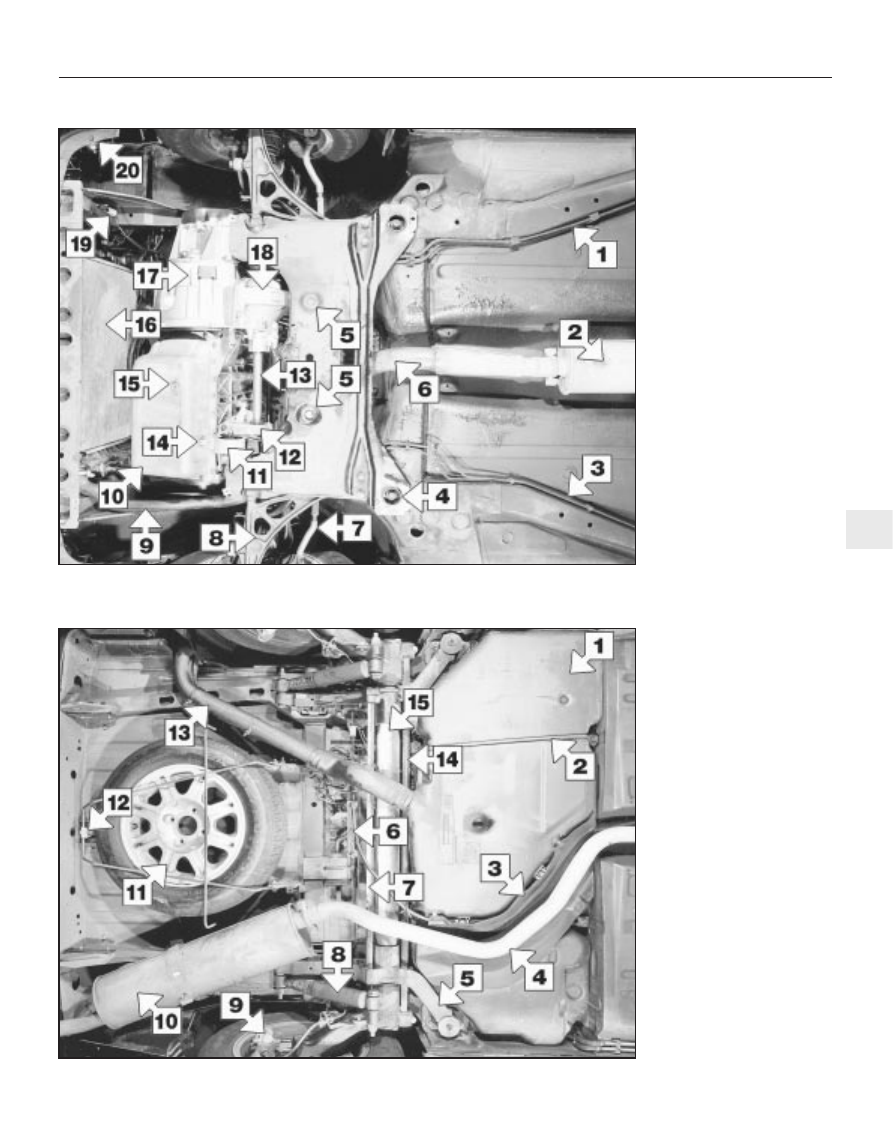
Rear underbody view of a 1905 cc engine model

1  Fuel tank
2  Fuel tank supporting strap
3  Heat shield
4  Exhaust pipe
5  Rear suspension side member
6  Handbrake cable equaliser 

mechanism

7  Rear suspension torsion bar
8  Rear shock absorber
9  Rear disc brake caliper
10  Exhaust rear silencer
11  Spare wheel (cover removed)
12  Spare wheel cradle support 

hook

13  Fuel filler hose
14  Rear anti-roll bar
15  Suspension cross-link

Front underbody view of a 1905 cc engine model

1  Fuel lines
2  Front exhaust silencer
3  Brake lines
4  Front subframe rear mounting
5  Steering rack mountings
6  Exhaust downpipe
7  Steering tack rod
8  Lower suspension arm
9  Radiator lower hose
10  Engine oil sump
11  Rear engine mounting
12  Driveshaft intermediate 

bearing housing

13  Right-hand driveshaft
14  Oil temperature sensor
15  Engine oil drain plug
16  Radiator
17  Transmission housing
18  Differential housing
19  Cooling fan resistor
20  Horn

Maintenance procedures

1•8

6000 Mile / 6 Month Service

1

Introduction

General information

This Chapter is designed to help the home
mechanic maintain his/her vehicle for safety,
economy, long life and peak performance.
The Chapter contains a master
maintenance schedule, followed by Sections
dealing specifically with each task in the
schedule. Visual checks, adjustments,
component renewal and other helpful items
are included. Refer to the accompanying
illustrations of the engine compartment and
the underside of the vehicle for the locations
of the various components.
Servicing your vehicle in accordance with
the mileage/time maintenance schedule and
the following Sections will provide a planned
maintenance programme, which should result
in a long and reliable service life. This is a
comprehensive plan, so maintaining some
items but not others at the specified service
intervals, will not produce the same results.
As you service your vehicle, you will
discover that many of the procedures can -
and should - be grouped together, because of
the particular procedure being performed, or
because of the close proximity of two
otherwise-unrelated components to one
another. For example, if the vehicle is raised
for any reason, the exhaust can be inspected
at the same time as the suspension and
steering components.
The first step in this maintenance

programme is to prepare yourself before the
actual work begins. Read through all the
Sections relevant to the work to be carried
out, then make a list and gather together all
the parts and tools required. If a problem is
encountered, seek advice from a parts
specialist, or a dealer service department.

2

Intensive maintenance

If, from the time the vehicle is new, the
routine maintenance schedule is followed
closely, and frequent checks are made of fluid
levels and high-wear items, as suggested
throughout this manual, the engine will be
kept in relatively good running condition, and
the need for additional work will be minimised.
It is possible that there will be times when
the engine is running poorly due to the lack of
regular maintenance. This is even more likely
if a used vehicle, which has not received
regular and frequent maintenance checks, is
purchased. In such cases, additional work
may need to be carried out, outside of the
regular maintenance intervals.
If engine wear is suspected, a compression
test will provide valuable information
regarding the overall performance of the main
internal components. Such a test can be used
as a basis to decide on the extent of the work
to be carried out. If, for example, a
compression test indicates serious internal
engine wear, conventional maintenance as
described in this Chapter will not greatly
improve the performance of the engine, and

may prove a waste of time and money, unless
extensive overhaul work is carried out first.
The following series of operations are those
most often required to improve the
performance of a generally poor-running
engine:

Primary operations

a) Clean, inspect and test the battery (see

“Weekly checks”).

b) Check all the engine-related fluids (see

“Weekly checks”).

c) Check the condition and tension of the

auxiliary drivebelt (Section 5).

d) Renew the spark plugs (Section 11).
e) Inspect the distributor cap and HT leads -

as applicable (Section 22).

f) Check the condition of the air cleaner

filter element, and renew if necessary
(Section 21).

g) Renew the fuel filter (Section 8).
h) Check the condition of all hoses, and

check for fluid leaks (Section 6).

i) Check the idle speed and mixture settings

- as applicable (Section 10).

If the above operations do not prove fully
effective, carry out the following secondary
operations:

Secondary operations

a) Check the charging system (Chapter 5A).
b) Check the ignition system (Chapter 5B).
c) Check the fuel system (Chapter 4).
d) Renew the distributor cap and rotor arm -

as applicable (Chapter 5B).

e) Renew the ignition HT leads - as

applicable (Section 22).

6000 Mile / 6 Month Service

3

Engine oil and filter renewal

1

Note: On models from 1994, the maker’s
specified interval for this procedure is 
9000 miles (15 000 km) or 12 months.
Note: A suitable square-section wrench may
be required to undo the sump drain plug on
some models. These wrenches cab be
obtained from most motor factors or your
Peugeot dealer.
Frequent oil and filter changes are the most
important preventative maintenance
procedures which can be undertaken by the
DIY owner. As engine oil ages, it becomes
diluted and contaminated, which leads to
premature engine wear.
Before starting this procedure, gather
together all the necessary tools and materials.

Also make sure that you have plenty of clean
rags and newspapers handy, to mop up any
spills. Ideally, the engine oil should be warm,
as it will drain better, and more built-up
sludge will be removed with it. Take care,
however, not to touch the exhaust or any
other hot parts of the engine when working
under the vehicle. To avoid any possibility of
scalding, and to protect yourself from
possible skin irritants and other harmful
contaminants in used engine oils, it is
advisable to wear gloves when carrying out
this work. Access to the underside of the
vehicle will be greatly improved if it can be
raised on a lift, driven onto ramps, or jacked
up and supported on axle stands (see
“Jacking and Vehicle Support”). Whichever
method is chosen, make sure that the vehicle
remains level, or if it is at an angle, so that the
drain plug is at the lowest point. Where
necessary remove the splash guard from
under the engine.

Slacken the drain plug about half a turn; on
some models, a square-section wrench may
be needed to slacken the plug (see
illustration)
. Position the draining container
under the drain plug, then remove the plug
completely. If possible, try to keep the plug

3.3  Slackening the sump drain plug with a

square-section wrench

pressed into the sump while unscrewing it by
hand the last couple of turns (see Haynes
Hint) 
.
Recover the sealing ring from the drain
plug.
Allow some time for the old oil to drain,
noting that it may be necessary to reposition
the container as the oil flow slows to a trickle.
After all the oil has drained, wipe off the
drain plug with a clean rag. Check the sealing
washer for condition, and renew it if
necessary. Clean the area around the drain
plug opening, then refit and tighten the plug.
If the filter is also to be renewed, move the
container into position under the oil filter
which is located on the front side of the
cylinder block, below the inlet manifold.
Using an oil filter removal tool if necessary,
slacken the filter initially, then unscrew it by
hand the rest of the way (see illustration).
Empty the oil from the old filter into the
container, and discard the filter.
Use a clean rag to remove all oil, dirt and
sludge from the filter sealing area on the
engine. Check the old filter to make sure that
the rubber sealing ring hasn’t stuck to the
engine. If it has, carefully remove it.
10 Apply a light coating of clean engine oil to
the sealing ring on the new filter, then screw it
into position on the engine. Tighten the filter
firmly by hand only - do not use any tools.
Wipe clean the filter and sump drain plug.

11 Remove the old oil and all tools from
under the car, then lower the car to the
ground (if applicable).
12 Remove the dipstick then unscrew the oil
filler cap from the cylinder head cover. Fill the
engine, using the correct grade and type of oil
(see  “Weekly checks”). An oil can spout or
funnel may help to reduce spillage. Pour in
half the specified quantity of oil first, then wait
a few minutes for the oil to fall to the sump.
Continue adding oil a small quantity at a time
until the level is up to the lower mark on the
dipstick. Finally, bring the level up to the
upper mark on the dipstick. Insert the
dipstick, and refit the filler cap.
13 Start the engine and run it for a few
minutes; check for leaks around the oil filter
seal and the sump drain plug. Note that there
may be a delay of a few seconds before the oil
pressure warning light goes out when the
engine is first started, as the oil circulates
through the engine oil galleries and the new oil
filter, before the pressure builds up.
14 Switch off the engine, and wait a few
minutes for the oil to settle in the sump once
more. With the new oil circulated and the filter
completely full, recheck the level on the
dipstick, and add more oil as necessary.
15 Dispose of the used engine oil safely, with
reference to “General Repair Procedures” in
the Reference section of this manual.

4

Automatic transmission fluid
level check

1

Note: On models from 1994, the maker’s
specified interval for this procedure is 
9000 miles (15 000 km) or 12 months.
Take the vehicle on a short journey, to
warm the transmission up to normal operating
temperature, then park the vehicle on level
ground. The fluid level is checked using the
dipstick located at the front of the engine
compartment, directly in front of the
engine/transmission. The dipstick top is
brightly-coloured (usually orange) for easy
identification.
With the engine idling and the selector lever
in the “P” (Park) position, withdraw the
dipstick from the tube, and wipe all the fluid
from its end with a clean rag or paper towel.
Insert the clean dipstick back into the tube as
far as it will go, then withdraw it once more.
Note the fluid level on the end of the dipstick;
it should be between the upper and lower
marks (see illustrations).

If topping-up is necessary, add the required
quantity of the specified fluid to the
transmission via the dipstick tube. Use a
funnel with a fine mesh gauze, to avoid
spillage, and to ensure that no foreign matter
enters the transmission. Note: Never overfill
the transmission so that the fluid level is above
the upper mark.
After topping-up, take the vehicle on a
short run to distribute the fresh fluid, then
recheck the level again, topping-up if
necessary.
Always maintain the level between the two
dipstick marks. If the level is allowed to fall
below the lower mark, fluid starvation may
result, which could lead to severe
transmission damage.
Frequent need for topping-up indicates that
there is a leak, which should be found and
corrected before it becomes serious.

5

Auxiliary drivebelt check 
and renewal

3

Note: On models from 1994, the maker’s
specified interval for this procedure is 
18 000 miles (30 000 km).
Note: Peugeot specify the use of a special
electronic tool (SEEM C.TRONIC type 105 belt
tensioning measuring tool) to correctly set the
auxiliary drivebelt tension. If access to this
equipment cannot be obtained, an
approximate setting can be achieved using
the method described below. If the method
described is used, the tension should be

6000 Mile / 6 Month Service  

1•9

4.2a  Withdrawing the automatic

transmission dipstick

4.2b  Automatic transmission fluid dipstick

lower (a) and upper (b) fluid level markings

3.8  Using an oil filter removal tool to

slacken the oil filter

1

As the engine oil drain plug releases
from the threads, move it away sharply
so the stream of oil issuing from the
sump runs into the container, not up
your sleeve! 

Note: It is
antisocial and
illegal to dump oil
down the drain.
To find the
location of your
local oil recycling
bank, call this
number free.

checked using the special electronic tool at
the earliest opportunity.
Except for XU9J4 16-valve engines, all
models are fitted with one auxiliary drivebelt
driven from the crankshaft pulley on the right-
hand side of the engine. On non-air
conditioning models the belt drives the
alternator and power steering pump and its
tension is adjusted manually. On models fitted
with air conditioning it drives the alternator,
power steering pump and the air conditioning
compressor. On XU9J4 models a separate
drivebelt drives the power steering pump from
a pulley on the end of the camshaft.

Checking the 
auxiliary drivebelt condition

Except XU9J4 16-valve 
power steering drivebelt

Apply the handbrake, then jack up the front
of the car and support it on axle stands (see
Jacking and Vehicle Support”). Remove the
right-hand front roadwheel.
Remove the engine undercover and
wheelarch cover as applicable.
Using a suitable socket and extension bar
fitted to the crankshaft sprocket/pulley bolt,
rotate the crankshaft so that the entire length
of the drivebelt can be examined. Examine the
drivebelt for cracks, splitting, fraying or
damage. Check also for signs of glazing (shiny
patches) and for separation of the belt plies.
Renew the belt if worn or damaged.
If the condition of the belt is satisfactory, on
models where the belt is adjusted manually,
check the drivebelt tension as described
below. On models with an automatic spring-
loaded tensioner, there is no need to check
the drivebelt tension.

XU9J4 16-valve 
power steering drivebelt

The power steering drivebelt is positioned
on the left-hand end of the cylinder head.
Examine the full length of the drivebelt for
cracks, splitting, fraying or damage. If
necessary turn the engine with a spanner on
the crankshaft pulley or by engaging 4th gear
and pushing the car (for safety, the car must
be on level ground). Check also for signs of
glazing (shiny patches) and for separation of
the belt plies.
If the condition of the belt is satisfactory,
check the drivebelt tension as described later
in this Section.

Auxiliary drivebelt 
(early models) - removal,
refitting and tensioning

Removal

Loosen the alternator pivot and link bolts,
then unscrew the adjuster bolt to release the
drivebelt tension (see illustration).
Remove the drivebelt from the alternator,
crankshaft and where necessary the power
steering pulleys.

Refitting and tensioning

10 Locate the drivebelt on the pulleys making
sure it is correctly engaged with the grooves.
11 The belt tension must be adjusted so that
with moderate thumb pressure applied mid-
way along the belt’s longest run, it can be
deflected by approximately 6.0 mm. Turn the
adjuster bolt in or out to obtain the correct
tension, then tighten the pivot and link bolts
(see illustration).

Auxiliary drivebelt 
(models with a manually-
adjusted tensioning pulley) -
removal, refitting and tensioning

Removal

12 If not already done, proceed as described
in paragraphs 2 and 3.
13 Disconnect the battery negative lead.
14 Slacken the tensioner pulley bracket
adjustment/mounting bolts (one located in the
middle of the pulley and the other located
below on the bracket (see illustration).
15 Fully tighten the adjustment bolt to its
stop, then slip the drivebelt from the pulleys
(see illustration).

Refitting

16 If the belt is being renewed, ensure that
the correct type is used. Fit the belt around
the pulleys, and take up the slack in the belt
by tightening the adjuster bolt. Ensure that the
ribs on the belt are correctly engaged with the
grooves in the pulleys.
17 Tension the drivebelt as described in the
following paragraphs.

Tensioning

18 If not already done, proceed as described
in paragraphs 2 and 3.
19 Correct tensioning of the drivebelt will
ensure that it has a long life. A belt which is
too slack will slip and perhaps squeal.
Beware, however, of overtightening, as this
can cause wear in the alternator bearings.
20 The belt should be tensioned so that,
under firm thumb pressure, there is approxi-
mately 5.0 mm of free movement at the mid-
point between the pulleys on the longest belt
run (see the note at the start of this Section).
21 To adjust, unscrew the adjustment bolt
until the tension is correct, then rotate the
crankshaft a couple of times, and recheck the
tension. Securely tighten the tensioner pulley
bracket adjustment/mounting bolts.
22 Reconnect the battery negative lead.
23 Refit the engine undercover and
wheelarch cover. Refit the roadwheel, and
lower the vehicle to the ground.

Auxiliary drivebelt 
(models with an automatic
spring-loaded tensioner pulley) -
removal, refitting and tensioning

Removal

24 If not already done, proceed as described
in paragraphs 2 and 3.
25 Disconnect the battery negative lead.
26 Using a square drive key in the square
hole in the bottom of the automatic adjuster
bracket, turn the bracket anticlockwise to
release the tension on the belt. Hold the
bracket in this position by inserting a 4.0 mm

1•10

6000 Mile / 6 Month Service

5.8  Loosening the alternator adjustment

bolts (early models)

5.14  Tensioner pulley bracket lower

mounting bolt (arrowed)

5.15  Auxiliary drivebelt tension adjustment

bolt (arrowed)

5.11  Alternator drivebelt deflection (A)


содержание   ..  5  6  7  8   ..