Opel Frontera UBS. Manual - part 541
7A–33
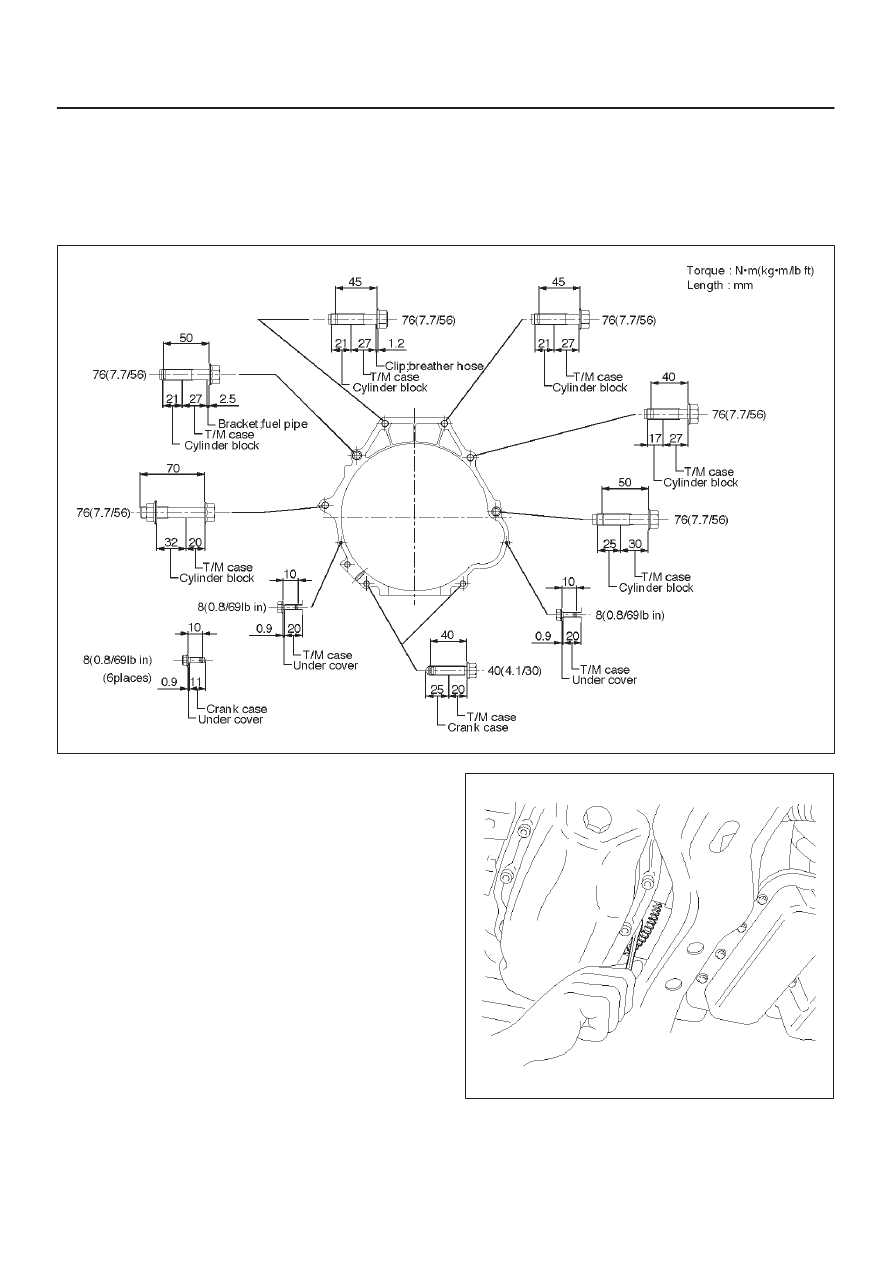
AUTOMATIC TRANSMISSION (4L30–E)
27. Remove transmission assembly (18).
Installation
1. Slowly raise transmission jack until front of the
transmission is aligned with rear of the engine, then
install transmission assembly.
2. Tighten engine transmission bolts to the specified
torque.
F07RW041
3. Support transfer case with a jack, and remove the
transmission jack.
4. Install flywheel torque converter bolts (6 pieces) by
turning crankshaft.
Torque: 54 N
•
m (5.5 kg·m/40 lb ft)
NOTE: Do not reuse the flywheel torque converter bolt.
240RW005