Opel Frontera UBS. Manual - part 539
7A–25
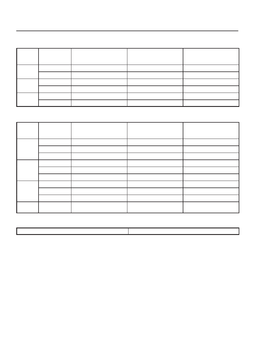
AUTOMATIC TRANSMISSION (4L30–E)
“Power mode”
Upshift
Range
Throttle
opening
1
→
2
(First Gear) (Second Gear)
Km/h (mph)
2
→
3
(Second Gear) (Third Gear)
Km/h (mph)
3
→
4
(Third Gear) (Fourth Gear)
Km/h (mph)
D
Fully opened
41
∼
47 (25
∼
29)
79
∼
85 (49
∼
53)
125
∼
131 (78
∼
81)
(Drive)
Half throttle
36
∼
42 (22
∼
26)
69
∼
75 (43
∼
47)
119
∼
125 (74
∼
78)
3
Fully opened
41
∼
47 (25
∼
29)
79
∼
85 (49
∼
53)
—
(Third)
Half throttle
36
∼
42 (22
∼
26)
69
∼
75 (43
∼
47)
—
2
Fully opened
41
∼
47 (25
∼
29)
—
—
(Second)
Half throttle
36
∼
42 (22
∼
26)
—
—
Downshift
Range
Throttle
opening
1
←
2
(First Gear) (Second Gear)
Km/h (mph)
2
←
3
(Second Gear) (Third Gear)
Km/h (mph)
3
←
4
(Third Gear) (Fourth Gear)
Km/h (mph)
D
Fully opened
28
∼
34 (17
∼
21)
70
∼
76 (43
∼
47)
115
∼
121 (71
∼
75)
D
(Drive)
Half throttle
20
∼
26 (12
∼
16)
46
∼
52 (29
∼
32)
90
∼
96 (56
∼
60)
(Drive)
Fully closed
12
∼
18 (7
∼
11)
22
∼
28 (14
∼
17)
43
∼
50 (27
∼
31)
3
Fully opened
28
∼
34 (17
∼
21)
70
∼
76 (43
∼
47)
—
3
(Third)
Half throttle
20
∼
26 (12
∼
16)
46
∼
52 (29
∼
32)
—
(Third)
Fully closed
12
∼
18 (7
∼
11)
22
∼
28 (14
∼
17)
—
2
Fully opened
28
∼
34 (17
∼
21)
82
∼
88 (51
∼
55)
—
2
(Second)
Half throttle
20
∼
26 (12
∼
16)
82
∼
88 (51
∼
55)
—
(Second)
Fully closed
12
∼
18 (7
∼
11)
82
∼
88 (51
∼
55)
—
L
(First)
—
36
∼
42 (22
∼
26)
—
—
“Winter mode”
D range, winter mode ON
→
OFF
27
∼
33 Km/h (17
∼
20 mph)