Opel Frontera UBS. Manual - part 540


  Index      Opel     Opel Frontera UBS - service repair manual 1998-2002 year


Search            


Content   ..  538  539  540  541   ..


Opel Frontera UBS. Manual - part 540


7A–29

AUTOMATIC TRANSMISSION (4L30–E)

256RW015

3. Check the shift lock operation: 

a. Selector lever should not move out of “P” position

with ignition key in “Lock” position.

b. Selector lever can be moved out of “P” position with

ignition key in “ON” position only when brake pedal
is depressed.

c. Ignition key can be turned to “LOCK” position only

when selector lever is in “P” position (key can be
pulled out).

If (a) and (c) fail, readjust cable.  If (b) fails, readjust
connector wiring and brake pedal switch.
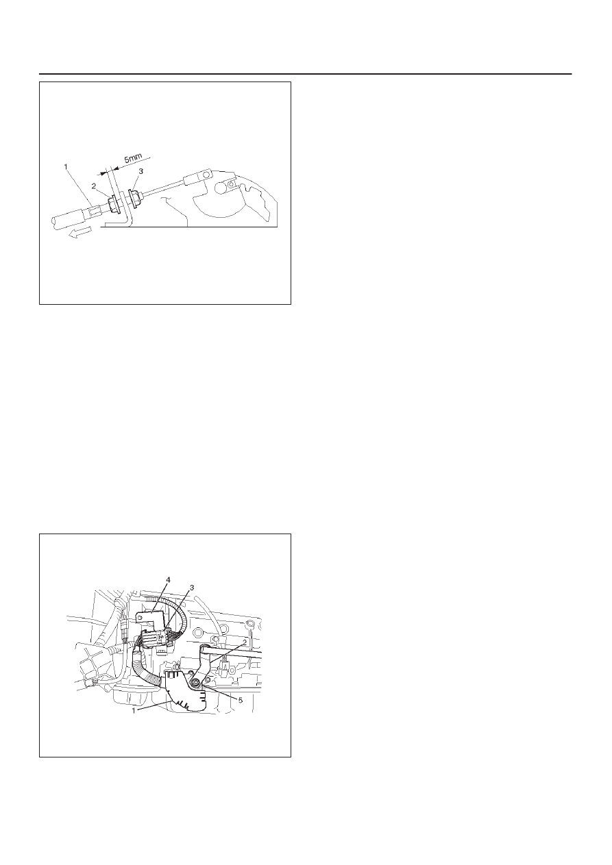
Mode Switch

Removal

1. Place selector lever in neutral.
2. Disconnect battery ground cable.
3. Remove mode switch cover (1).
4. Disconnect selector lever (2) from the mode switch.
5. Disconnect transmission harness from the mode

switch connector (3).

6. Remove bracket with mode switch connector from

the transmission case.

7. Remove mode switch connector (3) from the bracket

(4).

8. Remove two mode switch bolts and nut then remove

mode switch (5).

210RW008

Installation

To install, follow the removal steps in the reverse order,
noting the following points;

1. Torque

Mode switch bolt: 13 N

m (1.3 kg·m/113 lb in)

Selector lever nut: 23 N

m (2.3 kg·m/17 lb ft)

2. Mode switch setting procedure

Perform either of the following adjustment
procedures:

Procedure 1

a. Place selector lever in neutral.
b. Remove selector lever from the mode switch.
c. Remove the mode switch cover.
d. Loosen the two 10 mm screws.
e. Rotate the mode switch until the slot in the mode

switch housing aligns with the selector shaft
bushing, and insert a 3/32 in. (2.4 mm) drill bit or
punch (1) into the slot.

f. Tighten the screws to 13 N·m (1.3 kg·m/113 lb in).
g. After completing adjustment, snap the mode

switch cover into place.

h. Reinstall the selector lever.

7A–30

AUTOMATIC TRANSMISSION (4L30–E)

249RW001

Procedure 2

a. Place selector lever in neutral.
b. Disconnect transmission harness connector from

mode switch connector.

c. Remove mode switch connector with bracket from

the transmission case.

d. Connect multimeter (resistance mode) to

terminals 1(E) and 4(H) on mode switch connector.

e. Loosen two mounting screws.
f. Rotate mode switch slightly in both directions to

determine the range (approx. 5 degrees) of
electrical contact.

g. Position mode switch in middle of contact range.
h. Tighten two mounting screws.
i. Remove multimeter and install mode switch

harness connector with bracket to the
transmission case.

j. Connect transmission harness connector to mode

switch connector.

F07RW003

7A–31

AUTOMATIC TRANSMISSION (4L30–E)

Transmission (With Transfer Case)

Transmission And Associated Parts

240RW027

Legend

(1) Transfer Control Lever Knob
(2) Front Console
(3) Selector Lever Assembly
(4) Transfer Control Lever
(5) Transfer and Exhaust Protector
(6) Rear Propeller Shaft
(7) Front Propeller Shaft
(8) Harness Protector
(9) Rear Mount Nut

(10) Third Crossmember

(11) Exhaust Pipe

(12) Transmission Oil Cooler Pipe
(13) Starter
(14) Transmission Harness Connector
(15) Under Cover
(16) Torque Converter Bolt
(17) Engine Transmission Bolt
(18) Transmission Assembly

Removal

NOTE: Before remove transmission and transfer
assembly from vehicle, change the tansfer mode to 2WD
using push button on dash panel.

1. Remove engine hood.
2. Disconnect battery ground cable.
3. Remove transfer control lever knob (1) and

disconnect wiring harness connectors, then remove
front console (2).

7A–32

AUTOMATIC TRANSMISSION (4L30–E)

4. Disconnect shift lock cable from the selector lever

assembly side.

256RW012

5. Disconnect wiring harness connectors.
6. Disconnect shift control rod from the selector lever

assembly side.

256RW013

7. Remove selector lever assembly (3).
8. Remove transfer control lever (4).
9. Remove transfer and exhaust protector (5).

10. Remove rear propeller shaft (6).

11. Remove front propeller shaft (7).

12. Remove harness protector (8).
13. Support transfer case with a jack and remove two rear

mount nuts (9) from the 3rd crossmember side. 

14. Remove eight third crossmember bolts and third

crossmember (10).

15. Disconnect one oxygen sensor connector from the

transmission harness.

150RW002

16. Remove exhaust pipe (11).
17. Disconnect transmission oil cooler pipe (12) from A/T

side.

18. Remove oil pipe clamp  from torque converter

housing bracket.

253RW001

19. Loosen oil pipe clamp bolt at the engine mount side.
20. Remove starter (13).
21. Disconnect fuel pipe clamp bracket from

transmission side.

22. Disconnect transmission harness connectors (14)

from transmission, and transfer.

23. Remove flywheel under covers (3 pieces) (15) from

transmission case.

24. Lower the front of the transmission a little, then

remove flywheel torque converter fixing bolts (6
pieces) (16) by turning crankshaft.

25. Support the transmission with a transmission jack,

and hoist engine with a chain block.

26. Remove engine transmission fixing bolts (17). 


Content   ..  538  539  540  541   ..