Opel Frontera UBS. Manual - part 264


  Index      Opel     Opel Frontera UBS - service repair manual 1998-2002 year


Search            


Content   ..  262  263  264  265   ..


Opel Frontera UBS. Manual - part 264


6C–12

ENGINE FUEL

Fuel Filler Cap

General Description

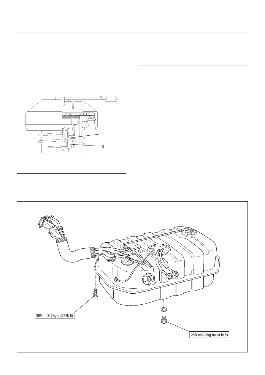
Fuel filler cap includes vacuum valve and pressure valve.
In case any high vacuum and any high pressure happen in
tank, each valve works to adjust the pressure to prevent
the tank from being damaged.

140RW021

Legend

(1) Vacuum Valve
(2) Pressure Valve

Inspection

Check the seal ring in the filler cap for presence of any
abnormality and for seal condition.
Replace the filler cap, if abnormal.

CAUTION: The fuel filler cap valves have
characteristics.
A defective valve, no valve at all or a valve with the
wrong characteristics will do a lot of harm to engine
operating characteristics; be sure to use the same
fuel filler cap as installed in this vehicle.

Main Data and Specifications

Torque Specification

N·m (Kg·m/lb ft)

ȡ

035RW141

ENGINE ELECTRICAL

6D1–1

ENGINE

ENGINE ELECTRICAL

CONTENTS

Service Precaution

6D1–1

. . . . . . . . . . . . . . . . . . . . . . 

Battery

6D1–2

. . . . . . . . . . . . . . . . . . . . . . . . . . . . . . . . . 

General Description

6D1–2

. . . . . . . . . . . . . . . . . . . . 

Diagnosis

6D1–2

. . . . . . . . . . . . . . . . . . . . . . . . . . . . . 

Battery Charging

6D1–3

. . . . . . . . . . . . . . . . . . . . . . 

Jump Starting

6D1–3

. . . . . . . . . . . . . . . . . . . . . . . . . 

Battery Removal

6D1–4

. . . . . . . . . . . . . . . . . . . . . . 

Battery Installation

6D1–4

. . . . . . . . . . . . . . . . . . . . . 

Main Data and Specifications

6D1–5

. . . . . . . . . . . 

Service Precaution

WARNING: IF SO EQUIPPED WITH A
SUPPLEMENTAL RESTRAINT SYSTEM (SRS),
REFER TO THE SRS COMPONENT AND WIRING
LOCATION VIEW IN ORDER TO DETERMINE
WHETHER YOU ARE PERFORMING SERVICE ON OR
NEAR THE SRS COMPONENTS OR THE SRS
WIRING. WHEN YOU ARE PERFORMING SERVICE
ON OR NEAR THE SRS COMPONENTS OR THE SRS
WIRING, REFER TO THE SRS SERVICE
INFORMATION. FAILURE TO FOLLOW WARNINGS
COULD RESULT IN POSSIBLE AIR BAG
DEPLOYMENT, PERSONAL INJURY, OR
OTHERWISE UNNEEDED SRS SYSTEM REPAIRS.

CAUTION: Always use the correct fastener in the
proper location. When you replace a fastener, use
ONLY the exact part number for that application.
ISUZU will call out those fasteners that require a
replacement after removal. ISUZU will also call out
the fasteners that require thread lockers or thread
sealant. UNLESS OTHERWISE SPECIFIED, do not
use supplemental coatings (Paints, greases, or other
corrosion inhibitors) on threaded fasteners or
fastener joint interfaces. Generally, such coatings
adversely affect the fastener torque and the joint
clamping force, and may damage the fastener. When
you install fasteners, use the correct tightening
sequence and specifications. Following these
instructions can help you avoid damage to parts and
systems.

SECTION

6D1–2

ENGINE ELECTRICAL

Battery

General Description

There are six battery fluid caps on top of the battery.
These are covered by a paper label.
The battery is completely sealed except for the six small
vent holes on the side. These vent holes permit the
escape of small amounts of gas generated by the battery.
This type of battery has the following advantages over
conventional batteries:

1. There is no need to add water during the entire

service life of the battery.

2. The battery protects itself against overcharging.

The battery will refuse to accept an extensive charge.
(A conventional battery will accept an excessive
charge, resulting in gassing and loss of battery fluid.)

3. The battery is much less vulnerable to self discharge

than a conventional type battery.

Diagnosis

1. Visual Inspection

Inspect the battery for obvious physical damage, such as
a cracked or broken case, which would permit electrolyte
loss.
Replace the battery if obvious physical damage is
discovered during inspection.
Check for any other physical damage and correct it as
necessary.

2. Hydrometer Check

There is a built–in hydrometer (Charge test indicator(1))
at the top of the battery. It is designed to be used during
diagnostic procedures.
Before trying to read the hydrometer, carefully clean the
upper battery surface.
If your work area is poorly lit, additional light may be
necessary to read the hydrometer.

a. BLUE RING OR DOT VISIBLE(5) – Go to Step 4. 
b. BLUE RING OR DOT NOT VISIBLE(4) – Go to Step

3. 

061RW001

3. Fluid Level Check

The fluid level should be between the upper level line(2)
and lower level line(3) on side of battery.

a. CORRECT FLUID LEVEL – Charge the battery.
b. BELOW LOWER LEVEL – Replace battery.

061RW001

4. Voltage Check

1. Put voltmeter test leads to battery terminals.

a. VOLTAGE IS 12.4V OR ABOVE – Go to Step 5. 
b. VOLTAGE IS UNDER 12.4V – Go to procedure (2)

below. 

2. Determine fast charge amperage from specification.

(See Main Data and Specifications in this section). 
Fast charge battery for 30 minutes at amperage rate
no higher than specified value.
Take voltage and amperage readings after charge.

a. VOLTAGE IS ABOVE 16V AT BELOW 1/3 OF

AMPERAGE RATE – Replace battery.

b. VOLTAGE IS ABOVE 16V AT ABOVE 1/3 OF

AMPERAGE  RATE – Drop charging voltage to
15V and charge for 10 – 15 hours. Then go to Step
5.

c. VOLTAGE IS BETWEEN 12V AND 16V –

Continue charging at the same rate for an
additional 3–1/2 hours. Then go to Step 5.

d. VOLTAGE BELOW 12V – Replace Battery.

5. Load Test

1. Connect a voltmeter and a battery load tester across

the battery terminals.

2. Apply 300 ampere load for 15 seconds to remove

surface charge from the battery. Remove load.

3. Wait 15 seconds to let battery recover. Then apply

specified load from specifications (See Main Data
and Specifications in this section).
Read voltage after 15 seconds, then remove load.

ENGINE ELECTRICAL

6D1–3

a. VOLTAGE DOES NOT DROP BELOW THE

MINIMUM LISTED IN THE TABLE – The battery is
good and should be returned to service.

b. VOLTAGE IS LESS THAN MINIMUM LISTED –

Replace battery.

ESTIMATED TEMPERATURE

MINIMUM

VOLTAGE

°

F

°

C

V

70

21

9.6

60

16

9.5

50

10

9.4

40

4

9.3

30

–1

9.1

20

–7

8.9

10

–12

8.7

0

–18

8.5

The battery temperature must be estimated by feel

and by the temperature the battery has been

exposed to for the preceding few hours.

Battery Charging

Observe the following safety precautions when charging
the battery:

1. Never attempt to charge the battery when the fluid

level is below the lower level line on the side of the
battery. In this case, the battery must be replaced.

2. Pay close attention to the battery during charging

procedure.
Battery charging should be discontinued or the rate of
charge reduced if the battery feels hot to the touch.
Battery charging should be discontinued or the rate of
charge reduced if the battery begins to gas or spew
electrolyte from the vent holes.

3. In order to more easily view the hydrometer blue dot

or ring, it may be necessary to jiggle or tilt the battery.

4. Battery temperature can have a great effect on

battery charging capacity.

5. The sealed battery used on this vehicle may be either

quick charged or slow charged in the same manner as
other batteries.
Whichever method you decide to use, be sure that
you completely charge the battery. Never partially
charge the battery.

Jump Starting

Jump Starting with an Auxiliary (Booster)
Battery

CAUTION: Never push or tow the vehicle in an
attempt to start it. Serious damage to the emission
system as well as other vehicle parts will result.

Treat both the discharged battery and the booster
battery with great care when using jumper cables.
Carefully follow the jump starting procedure, being
careful at all times to avoid sparking.

WARNING: FAILURE TO CAREFULLY FOLLOW THE
JUMP STARTING PROCEDURE COULD RESULT IN
THE FOLLOWING:

1. Serious personal injury, particularly to your eyes.
2. Property damage from a battery explosion, battery

acid, or an electrical fire.

3. Damage to the electronic components of one or both

vehicles particularly.

Never expose the battery to an open flame or electrical
spark. Gas generated by the battery may catch fire or
explode.
Remove any rings, watches, or other jewelry before
working around the battery. Protect your eyes by wearing
an approved set of goggles.
Never allow battery fluid to come in contact with your eyes
or skin.
Never allow battery fluid to come in contact with fabrics or
painted surfaces.
Battery fluid is a highly corrosive acid.
Should battery fluid come in contact with your eyes, skin,
fabric, or a painted surface, immediately and thoroughly
rinse the affected area with clean tap water.
Never allow metal tools or jumper cables to come in
contact with the positive battery terminal, or any other
metal surface of the vehicle. This will protect against a
short circuit.
Always keep batteries out of reach of young children.

Jump Starting Procedure

1. Set the vehicle parking brake.

If the vehicle is equipped with an automatic
transmission, place the selector level in the “PARK”
position.
If the vehicle is equipped with a manual transmission,
place the shift lever in the “NEUTRAL” position.
Turn “OFF” the ignition.
Turn “OFF” all lights and any other accessory
requiring electrical power.

2. Look at the built–in hydrometer.

If the indication area of the built–in hydrometer is
completely clear, do not try to jump start.

3. Attach the end of one jumper cable to the positive

terminal of the booster battery.
Attach the other end of the same cable to the positive
terminal of the discharged battery.
Do not allow the vehicles to touch each other. This will
cause a ground connection, effectively neutralizing
the charging procedure.
Be sure that the booster battery has a 12 volt rating.


Content   ..  262  263  264  265   ..