Opel Frontera UBS. Manual - part 265
6D1–4
ENGINE ELECTRICAL
4. Attach one end of the remaining cable to the negative
terminal of the booster battery.
Attach the other end of the same cable to a solid
engine ground (such as the air conditioning
compressor bracket or the generator mounting
bracket) of the vehicle with the discharged battery.
The ground connection must be at least 450 mm (18
in.) from the battery of the vehicle whose battery is
being charged.
WARNING: NEVER ATTACH THE END OF THE
JUMPER CABLE DIRECTLY TO THE NEGATIVE
TERMINAL OF THE DEAD BATTERY.
5. Start the engine of the vehicle with the good battery.
Make sure that all unnecessary electrical accessories
have been turned “OFF”.
6. Start the engine of the vehicle with the dead battery.
7. To remove the jumper cables, follow the above
directions in reverse order.
Be sure to first disconnect the negative cable from the
vehicle with the discharged battery.
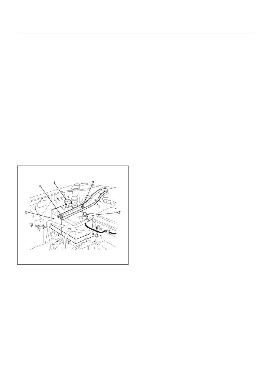
Battery Removal
061RS002
1. Remove negative cable (1).
2. Remove positive cable (2).
3. Remove retainer screw and rods (3).
4. Remove retainer (4).
5. Remove battery (5).
Battery Installation
1. Install battery (5).
2. Install retainer (4).
3. Instal retainer screw and rods (3).
NOTE: Make sure that the rod is hooked on the body
side.
4. Install positive cable (2).
5. Install negative cable (1).