Opel Frontera UE. Manual - part 1477


  Index      Opel     Opel Frontera UE - service repair manual 1999-2001 year


Search            


Content   ..  1475  1476  1477  1478   ..


Opel Frontera UE. Manual - part 1477


6E–123

6VD1 3.2L ENGINE DRIVEABILITY AND EMISSIONS

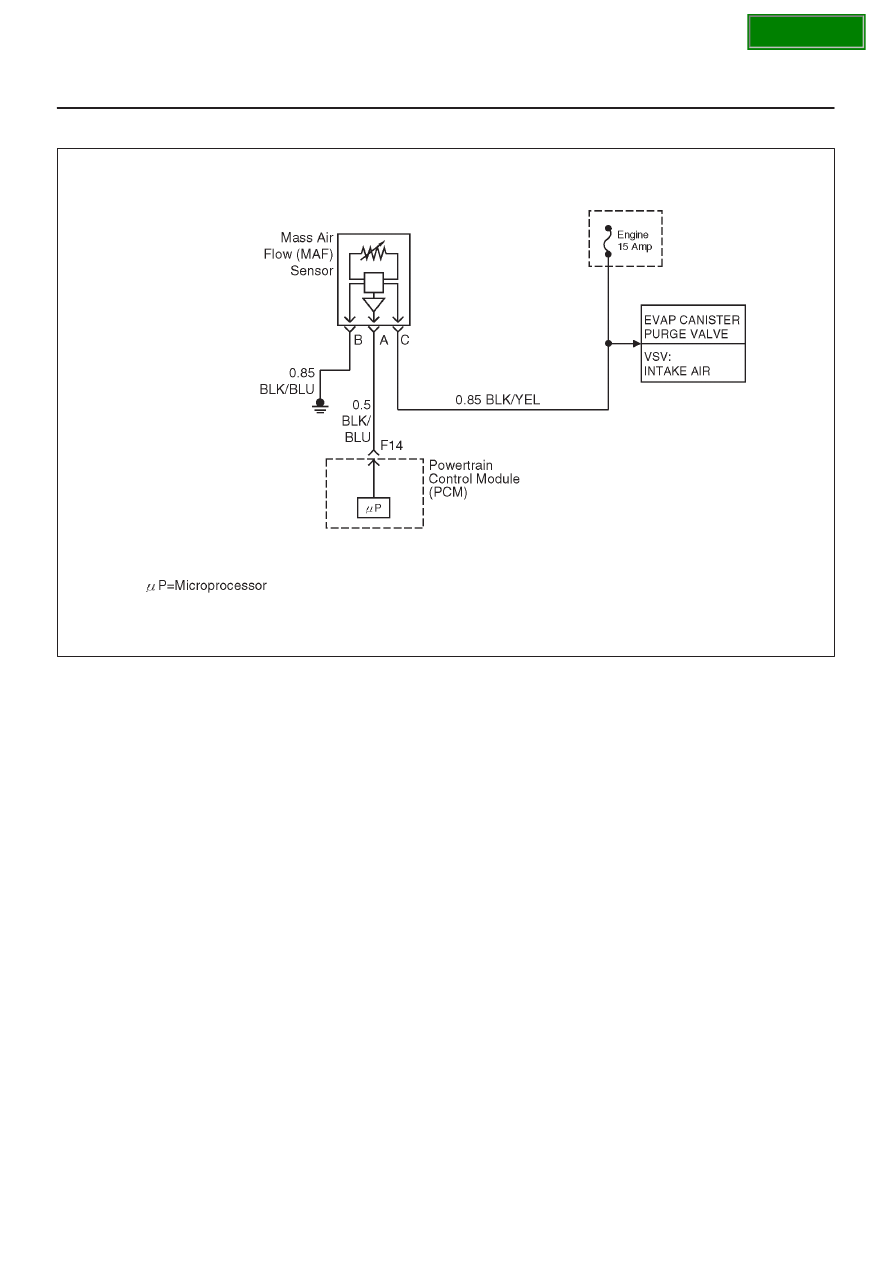
Diagnostic Trouble Code (DTC) P0103 MAF Sensor Circuit High Frequency

060R100112

Circuit Description

The mass air flow (MAF) sensor measures the amount of
air which passes through it into the engine during a given
time.  The powertrain control module (PCM) uses the
mass air flow information to monitor engine operating
conditions for fuel delivery calculations.  A large quantity
of air entering the engine indicates an accelerator or high
load situation, while a small quantity of air indicates
deceleration or idle.
The MAF sensor produces a frequency signal which can
be monitored using a Tech 2.  The frequency will vary
within a range of around 4 to 7g/s at idle to around 25 to 40
g/s at maximum engine load.  DTC P0103 will be set if the
signal from the MAF sensor is above the possible range of
a normally operating MAF sensor.

Conditions for Setting the DTC

D

The engine is running above 500 RPM for more than
10 seconds.

D

System voltage is above 11.5 volts.

D

MAF signal frequency is above 10 kHz for a total of 50
percent of the last 1000 samples monitored.  A sample
is taken every cylinder event.

Action Taken When the DTC Sets

D

The PCM will ON the MIL after second trip with
detected the fault.

D

The PCM calculates an airflow value based on idle air
control valve position, throttle position, RPM and
barometric pressure.

D

The PCM will store conditions which were present
when the DTC was set as Freeze Frame and in the
Failure Records data.

Conditions for clearing the MIL/DTC

D

The PCM will turn the MIL “OFF” on the third
consecutive trip cycle during which the diagnostic has
been run and the fault condition is no longer present.

D

A history DTC P0103 will clear after 40 consecutive
warm-up cycles have occurred without a fault.

D

DTC P0103 can be cleared by using the Tech 2 “Clear
Info” function.

Diagnostic Aids

If DTC P0103 cannot be duplicated, the information
included in the Failure Records data can be useful in
determining vehicle mileage since the DTC was last set.

Test Description

Number(s) below refer to the step number(s) on the
Diagnostic Chart.
2. This step verifies that the problem is present at idle.

SECTION

6E–124

6VD1 3.2L ENGINE DRIVEABILITY AND EMISSIONS

4. A frequency reading with the MAF sensor connector

disconnected indicates an electromagnetic
interference (EMI) related fault.

8. This vehicle is equipped with a PCM which utilizes

an electrically erasable programmable read only
memory (EEPROM).  When the PCM is being
replaced, the new PCM must be programmed.
Refer to 

PCM Replacement and Programming

Procedures in Powertrain Control Module (PCM)
and Sensors.

SECTION

6E–125

6VD1 3.2L ENGINE DRIVEABILITY AND EMISSIONS

DTC P0103 – MAF Sensor Circuit High Frequency


Step

Action

Value(s)

Yes

No

1

Was the “On-Board Diagnostic (OBD) System Check”
performed?

Go to 

Step 2

Go to 

OBD

System

Check

2

1. Ignition “ON”, engine “OFF”.
2. Review and record Tech 2 Failure Records data.
3. Operate the vehicle within Failure Records

conditions as noted.

4. Using a Tech 2, monitor “DTC” info for DTC P0103.

Does the Tech 2 indicate DTC P0103 failed this
ignition?

Go to 

Step 3

Refer to

Diagnostic

Aids

3

1. Start the engine.
2. With the engine idling, monitor “MAF Frequency”

display on the Tech 2.

Is “MAF Frequency” above the specified value?

40g/s

Go to 

Step 4

Go to 

Step 7

4

1. Ignition “OFF”.
2. Disconnect the MAF sensor connector.
3. Ignition “ON”, engine idling.
4. Using a Tech 2, monitor “MAF Frequency”.

Does the Tech 2 indicate a “MAF Frequency” at the
specified value?

0g/s

Go to 

Step 5

Go to 

Step 6

5

Replace the MAF sensor.

Is the action complete?

Verify repair

Go to 

Step 8

6

1. Check the MAF harness for incorrect routing near

high voltage components (solenoids, relays,
motors).

2. If incorrect routing is found,  correct the harness

routing.

Was a problem found?

Verify repair

Go to 

Step 6

7

1. With the engine idling, monitor “MAF Frequency”

display on the Tech 2.

2. Quickly snap open throttle to wide open throttle

while under a road load and record value.

Does the Tech 2 indicate “MAF Frequency” above the
specified value?

40g/s

Go to 

Step 5

Go to 

Step 8

8

Replace the PCM.

IMPORTANT: The replacement PCM must be
programmed.  Refer to 

On-Vehicle Service in

Powertrain Control Module and Sensors for
procedures.

And also refer to latest Service Bulletin.

Check to see if the Latest software is released or not.
And then Down Load the LATEST PROGRAMMED
SOFTWARE to the replacement PCM.

Is the action complete?

Verify repair

SECTION

6E–126

6VD1 3.2L ENGINE DRIVEABILITY AND EMISSIONS

Diagnostic Trouble Code (DTC) P0106 MAP System  Performance

060R100132

Circuit Description

The manifold absolute pressure (MAP) sensor responds
to changes in intake manifold pressure (vacuum).  The
MAP sensor signal voltage to the powertrain control
module (PCM) varies from below 2 volts at idle (high
vacuum) to above 4 volts at wide-open throttle (low
vacuum) at sea level.
The MAP sensor is used to determine manifold pressure
changes while the linear exhaust gas recirculation (EGR)
flow test diagnostic is being run (refer to DTC P0401),
engine vacuum level for some other diagnostics, and
barometric pressure (BARO).  The PCM compares the
MAP sensor signal to a calculated MAP based on throttle
position and various engine load factors.  If the PCM
detects a MAP signal that varies excessively above or
below the calculated value, DTC P0106 will set.

Conditions for Setting the DTC

D

No TP sensor DTCs are present.

D

Engine speed is steady, changing less then 100 RPM.

D

Engine speed is between 1000 rpm and 4000 rpm.

D

Throttle position is steady, throttle angle changes less
than 1%.

D

EGR flow rate is steady, changing less than 4%.

D

No change in brake switch, A/C clutch, TCC or power
steering pressure switch status.

D

Above conditions are met for longer than 1 second.

D

Calculated MAP signal indicates an value significantly
higher or lower than a predicated value based on

throttle position and engine RPM for a total of 12.5
seconds over 25 second period of time.

Action Taken When the DTC Sets

D

The PCM will illuminate the malfunction indicator lamp
(MIL) after the second consecutive trip in which the
fault is detected.

D

The PCM will default to a BARO value of 79.3 kPa.

D

The PCM will store conditions which were present
when the DTC was set as Freeze Frame and in the
Failure Records data.

Conditions for Clearing the MIL/DTC

D

The PCM will turn the MIL “OFF” on the third
consecutive trip cycle during which the diagnostic has
been run and the fault condition is no longer present.

D

A history DTC P0106 will clear after 40 consecutive
warm-up cycles have occurred without a fault.

D

DTC P0106 can be cleared by using the Tech 2 “Clear
Info” function.

Diagnostic Aids

Check for the following conditions:

D

Poor connection at PCM – Inspect harness connectors
for backed-out terminals, improper mating, broken
locks, improperly formed or damaged terminals, and
poor terminal-to-wire connection.

D

Damaged harness – Inspect the wiring harness for
damage.  If the harness appears to be OK, observe the
MAP display on the Tech 2 while moving connectors

SECTION


Content   ..  1475  1476  1477  1478   ..