Opel Frontera UE. Manual - part 1348


  Index      Opel     Opel Frontera UE - service repair manual 1999-2001 year


Search            


Content   ..  1346  1347  1348  1349   ..


Opel Frontera UE. Manual - part 1348


4C–14

DRIVE SHAFT SYSTEM

Shift On The Fly System

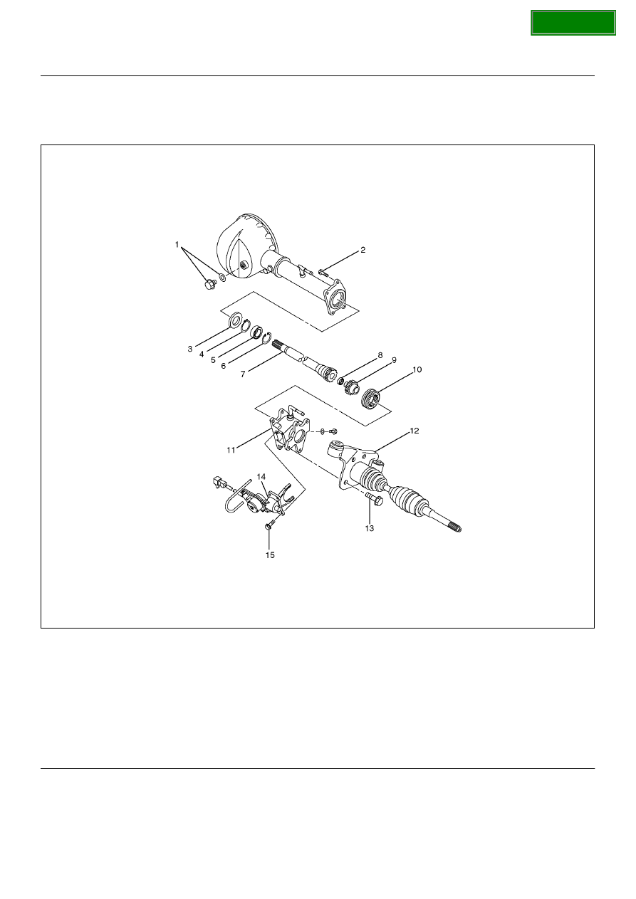
Shift On The Fly System and Associated Parts

412RY00007

Legend

EndOFCallout

Disassembly

1. Remove filler plug and gasket, drain oil.

2. Loosen mounting bracket fitting bolts and remove 

front axle drive shaft from front axle case.

3. Remove actuator assembly and draw out actuator 

ASM.

4. Remove housing.

5. Remove sleeve.

(1) Filler Plug
(2) Bolt
(3) Oil Seal
(4) Snap Ring(External)
(5) Inner Shaft Bearing
(6) Snap Ring(Internal)
(7) Inner Shaft
(8) Needle Bearing

(9) Clutch Gear

(10) Sleeve
(11) Housing
(12) Front Axle Drive Shaft(LH side) with Bracket
(13) Bolt
(14) Actuator Assembly
(15) Bolt

SECTION

DRIVE SHAFT SYSTEM

4C–15

6. Remove clutch gear.

7. Remove snap ring from front axle case by using 

snap ring pliers.

412RW017

8. Take out inner shaft from front axle case.

9. Remove snap ring from inner shaft by using snap 

ring pliers.

412RW016

10. Remove inner shaft bearing.

NOTE:  Be careful not to damage the shaft.

412RW015

11. Remove needle bearing from inner shaft by using a 

remover 5–8840–0027–0 and sliding hammer 5–
8840–0084–0.

412RS045

12. Remove oil seal from front axle case.

NOTE:  Be careful not to damage the front axle case.

SECTION

4C–16

DRIVE SHAFT SYSTEM

Inspection And Repair

Inspect the removed parts. If there are abnormalities 
such as wear and damage, take corrective action or 
replace.

Visual Check

1. Check and see if the inner shaft has such 

abnormalities as wear and damage.

412RW014

2. When inspecting the inner shaft, be sure to check 

and see if its splined part is twisted, worn, or 
cracked. If so, replace with a new shaft. In case 
such an abnormality in its gear part  (a slide with 
sleeve), replace the shaft.

420RS008

Inner Shaft Run–Out

With both end centers supported, rotate the shaft slowly 
and measure deflection with a dial gauge.

Limit:0.5mm (0.02in)

NOTE:  Do not heat the shaft to correct its bend.

412RS026

Inner Shaft Bearing

412RW006

Legend

EndOFCallout

1. Inspect the state of inner shaft bearing. If any 

abnormality such as smoothlessness is found, 
replace with a new inner shaft bearing.

2. Insert a clutch gear and check the state of needle 

bearing.

3. If there is an abnormality such as smoothlessness, 

replace the needle bearing.

(1) Inner Shaft Bearing
(2) Inner Shaft
(3) Clutch Gear

SECTION

DRIVE SHAFT SYSTEM

4C–17

Sleeve Condition

Check and see that there is not wear damage, or 
cracking in the sleeve.

NOTE:  Close inspection of the groove and inner gear 
are required because those are important parts.

Sleeve Function

412RY00039

Operate the sleeve with the inner shaft combined with 
the clutch gear and if smoothlessness is felt, replace the 
sleeve.

NOTE:  Gear oil should be applied to the contact 
surface of gear.
Check the width of sleeve center groove.

Limit:7.1mm (0.28in)

412RW022

Clutch Gear Condition

Check and see that there is not wear, damage, crack, or 
any other abnormality in the clutch gear.

Clutch Gear Function

412RY00038

If there is an abnormality such as roughness when 
operated in combination with sleeve, replace the clutch 
gear.

NOTE:  When inspecting, gear oil should be applied to 
the contact surface of gear.

Clutch Gear Journal Diameter

Make sure of the size illustrated.

Limit:36.98mm (1.456in)

412RY00037

SECTION


Content   ..  1346  1347  1348  1349   ..