Content .. 1345 1346 1347 1348 ..
Opel Frontera UE. Manual - part 1347
4C–10
DRIVE SHAFT SYSTEM
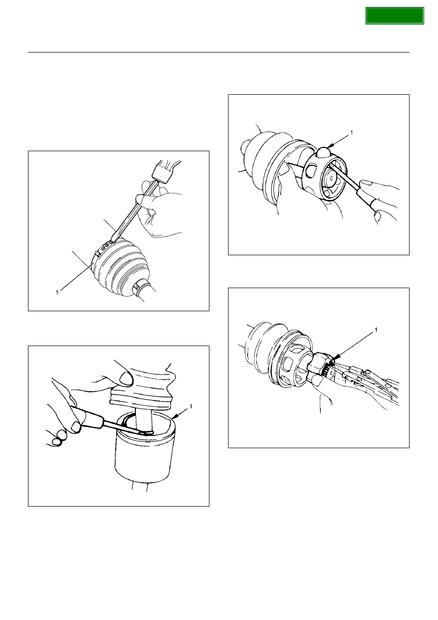
Disassembly
NOTE: For the left side, follow the same steps as right
side.
1. Use a hammer and chisel to remove the 3 pawls
(above the large and small boot bands on the DOJ
side).
CAUTION: Take care not to damage the bellows
during band removal.
412R100011
2. Remove band(1).
3. Pry off circlip (1) with a screwdriver or equivalent.
412RS010
4. Remove drive shaft joint assembly.
5. Remove the six balls (1) with a screwdriver or
equivalent.
412RS012
6. Using snap ring pliers, remove the snap ring (1)
fastening the ball retainer to the center shaft.
412RS013