Nissan Frontier D40. Manual - part 490


  Index      Nissan     Nissan Frontier D40 (2010 year) - Service and Repair Manual


Search            


Content   ..  488  489  490  491   ..


Nissan Frontier D40. Manual - part 490


P0182, P0183 FTT SENSOR

EC-651

< COMPONENT DIAGNOSIS >

[VQ40DE]

C

D

E

F

G

H

I

J

K

L

M

A

EC

N

P

O

NG

>> Go to 

MWI-32, "Component Function Check"

.

2.

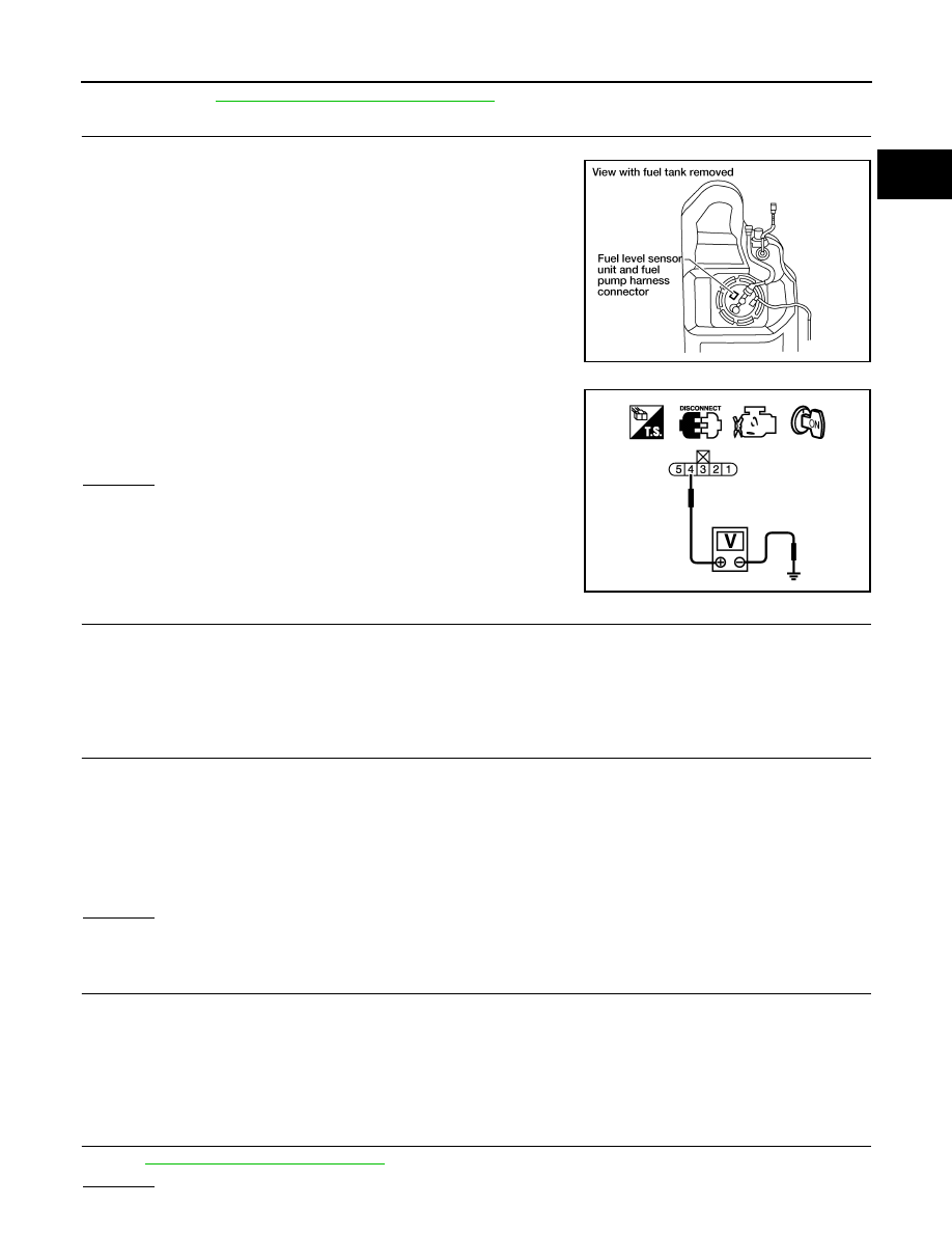
CHECK FUEL TANK TEMPERATURE SENSOR POWER SUPPLY CIRCUIT

1.

Turn ignition switch OFF.

2.

Disconnect “fuel level sensor unit and fuel pump” harness con-
nector.

3.

Turn ignition switch ON.

4.

Check voltage between “fuel level sensor unit and fuel pump”
terminal 4 and ground with CONSULT-III or tester.

OK or NG

OK

>> GO TO 4.

NG

>> GO TO 3.

3.

DETECT MALFUNCTIONING PART

Check the following.
• Harness connectors E41, C1
• Harness for open or short between ECM and “fuel level sensor unit and fuel pump”

>> Repair harness or connector.

4.

CHECK FUEL TANK TEMPERATURE SENSOR GROUND CIRCUIT FOR OPEN AND SHORT

1.

Turn ignition switch OFF.

2.

Disconnect combination meter harness connector.

3.

Check harness continuity between “fuel level sensor unit and fuel pump” terminal 2 and combination
meter terminal 9. Refer to Wiring Diagram.

4.

Also check harness for short to ground and short to power.

OK or NG

OK

>> GO TO 6.

NG

>> GO TO 5.

5.

DETECT MALFUNCTIONING PART

Check the following.
• Harness connectors E41, C1
• Harness connectors E152, M31
• Harness for open or short between “fuel level sensor unit and fuel pump” and combination meter

>> Repair open circuit or short to ground or short to power in harness or connector.

6.

CHECK FUEL TANK TEMPERATURE SENSOR

Refer to 

EC-652, "Component Inspection"

.

OK or NG

BBIA0545E

Voltage: Approximately 5V

PBIB0932E

Continuity should exist.

EC-652

< COMPONENT DIAGNOSIS >

[VQ40DE]

P0182, P0183 FTT SENSOR

OK

>> GO TO 7.

NG

>> Replace fuel level sensor unit.

7.

CHECK INTERMITTENT INCIDENT

Refer to 

GI-46, "Intermittent Incident"

.

>> INSPECTION END

Component Inspection

INFOID:0000000005273620

FUEL TANK TEMPERATURE SENSOR

1.

Remove fuel level sensor unit.

2.

Check resistance between “fuel level sensor unit and fuel pump”
terminals 2 and 4 by heating with hot water or heat gun as
shown in the figure.

Temperature 

°

C (

°

F)

Resistance k

20 (68)

2.3 - 2.7

50 (122)

0.79 - 0.90

PBIB2663E

P0222, P0223 TP SENSOR

EC-653

< COMPONENT DIAGNOSIS >

[VQ40DE]

C

D

E

F

G

H

I

J

K

L

M

A

EC

N

P

O

P0222, P0223 TP SENSOR

Component Description

INFOID:0000000005273621

Electric throttle control actuator consists of throttle control motor,
throttle position sensor, etc. The throttle position sensor responds to
the throttle valve movement.
The throttle position sensor has the two sensors. These sensors are
a kind of potentiometers which transform the throttle valve position
into output voltage, and emit the voltage signal to the ECM. In addi-
tion, these sensors detect the opening and closing speed of the
throttle valve and feed the voltage signals to the ECM. The ECM
judges the current opening angle of the throttle valve from these sig-
nals and the ECM controls the throttle control motor to make the
throttle valve opening angle properly in response to driving condi-
tion.

On Board Diagnosis Logic

INFOID:0000000005273622

These self-diagnoses have the one trip detection logic.

FAIL-SAFE MODE

When the malfunction is detected, ECM enters fail-safe mode and the MIL illuminates.

DTC Confirmation Procedure

INFOID:0000000005273623

NOTE:
If DTC Confirmation Procedure has been previously conducted, always perform the following before conduct-
ing the next step.

1.

Turn ignition switch OFF and wait at least 10 seconds.

2.

Turn ignition switch ON.

3.

Turn ignition switch OFF and wait at least 10 seconds.

TESTING CONDITION:
Before performing the following procedure, confirm that battery voltage is more than 10V at idle.

4.

Start engine and let it idle for 1 second.

5.

Check DTC.

6.

If DTC is detected, go to 

EC-653, "Diagnosis Procedure"

.

Diagnosis Procedure

INFOID:0000000005273624

1.

CHECK GROUND CONNECTIONS

1.

Turn ignition switch OFF.

PBIB0145E

DTC No.

Trouble diagnosis name

DTC detecting condition

Possible cause

P0222
0222

Throttle position sensor 
1 circuit low input

An excessively low voltage from the TP sensor 
1 is sent to ECM.

• Harness or connectors

(The TP sensor 1 circuit is open or short-
ed.)
(The APP sensor 2 circuit is shorted.)

• Electric throttle control actuator

(TP sensor 1)

• Accelerator pedal position sensor.

(APP sensor 2)

P0223
0223

Throttle position sensor 
1 circuit high input

An excessively high voltage from the TP sensor 
1 is sent to ECM.

Engine operation condition in fail-safe mode

The ECM controls the electric throttle control actuator in regulating the throttle opening in order for the idle position to be within +10 
degrees.
The ECM regulates the opening speed of the throttle valve to be slower than the normal condition.
So, the acceleration will be poor. 

EC-654

< COMPONENT DIAGNOSIS >

[VQ40DE]

P0222, P0223 TP SENSOR

2.

Loosen and retighten three ground screws on the body. Refer to 

EC-549, "Ground Inspection"

.

OK or NG

OK

>> GO TO 2.

NG

>> Repair or replace ground connections.

2.

CHECK THROTTLE POSITION SENSOR 1 POWER SUPPLY CIRCUIT-I

1.

Disconnect electric throttle control actuator harness connector.

2.

Turn ignition switch ON.

3.

Check voltage between electric throttle control actuator terminal
2 and ground with CONSULT-III or tester.

OK or NG

OK

>> GO TO 7.

NG

>> GO TO 3.

3.

CHECK THROTTLE POSITION SENSOR 1 POWER SUPPLY CIRCUIT-II

1.

Turn ignition switch OFF.

2.

Disconnect ECM harness connector.

3.

Check harness continuity between electric throttle control actuator terminal 2 and ECM terminal 47.
Refer to Wiring Diagram.

OK or NG

OK

>> GO TO 4.

NG

>> Repair open circuit.

4.

CHECK THROTTLE POSITION SENSOR 1 POWER SUPPLY CIRCUIT-III

Check harness for short to power and short to ground, between the following terminals.

BBIA0539E

BBIA0543E

Voltage: Approximately 5V

PBIB2604E

Continuity should exist.

ECM terminal

Sensor terminal

Reference Wiring Diagram

47

Electric throttle control actuator terminal 2

EC-897

91

APP sensor terminal 1


Content   ..  488  489  490  491   ..