Nissan Frontier D40. Manual - part 489
P0181 FTT SENSOR
EC-647
< COMPONENT DIAGNOSIS >
[VQ40DE]
C
D
E
F
G
H
I
J
K
L
M
A
EC
N
P
O
P0181 FTT SENSOR
Component Description
INFOID:0000000005273611
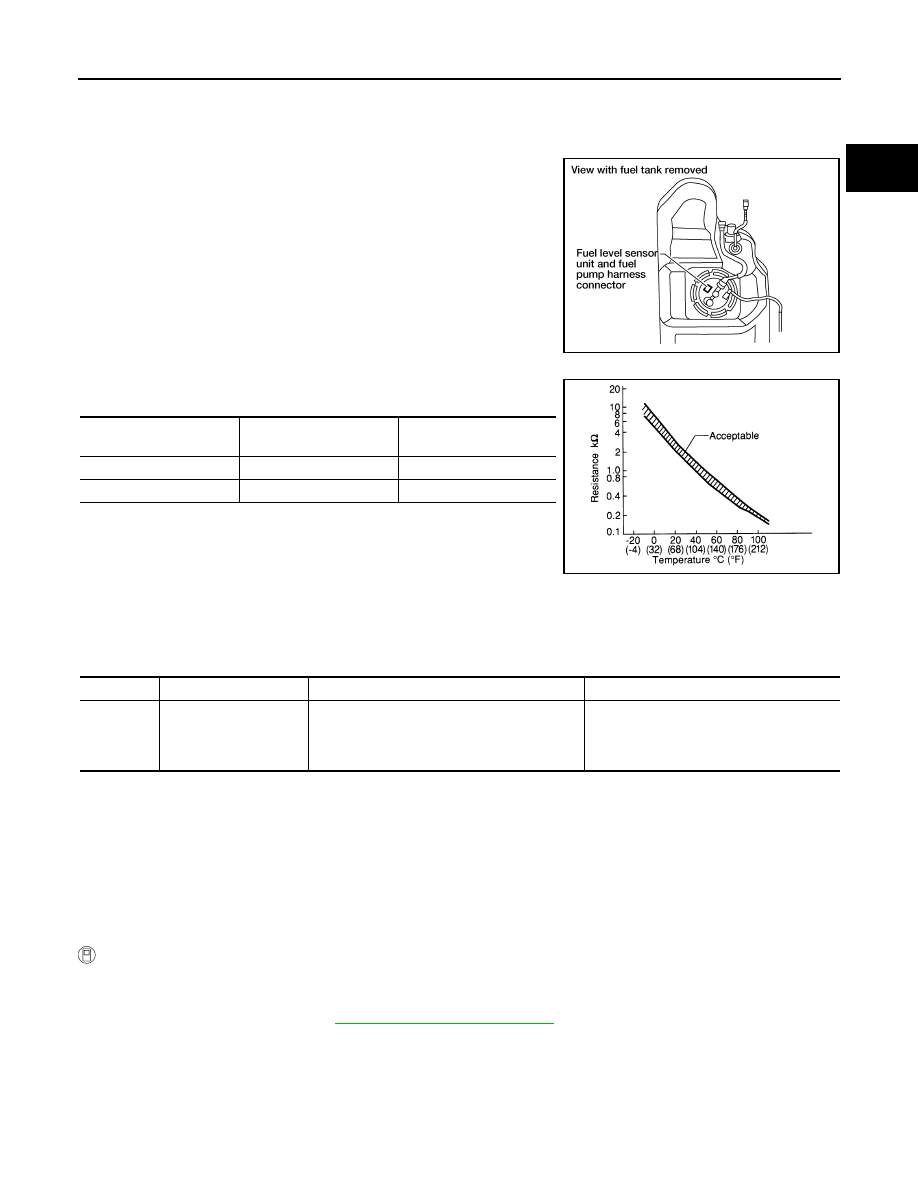
The fuel tank temperature sensor is used to detect the fuel tempera-
ture inside the fuel tank. The sensor modifies a voltage signal from
the ECM. The modified signal returns to the ECM as the fuel temper-
ature input. The sensor uses a thermistor which is sensitive to the
change in temperature. The electrical resistance of the thermistor
decreases as temperature increases.
<Reference data>
*: This data is reference value and is measured between ECM terminal 107 (fuel tank
temperature sensor) and ground.
CAUTION:
Never use ECM ground terminals when measuring input/output
voltage. Doing so may result in damage to the ECM's transistor.
Use a ground other than ECM terminals, such as the ground.
On Board Diagnosis Logic
INFOID:0000000005273612
DTC Confirmation Procedure
INFOID:0000000005273613
NOTE:
If DTC Confirmation Procedure has been previously conducted, always perform the following before conduct-
ing the next step.
1.
Turn ignition switch OFF and wait at least 10 seconds.
2.
Turn ignition switch ON.
3.
Turn ignition switch OFF and wait at least 10 seconds.
WITH CONSULT-III
1.
Turn ignition switch ON and wait at least 10 seconds.
2.
Check 1st trip DTC.
If 1st trip DTC is detected, go to
If 1st trip DTC is not detected, go to following step.
3.
Select “DATA MONITOR” mode with CONSULT-III.
4.
Check “COOLAN TEMP/S” value.
If “COOLAN TEMP/S” is less than 60
°
C (140
°
F), the result will be OK.
If “COOLAN TEMP/S” is above 60
°
C (140
°
F), go to the following step.
5.
Cool engine down until “COOLAN TEMP/S” is less than 60
°
C (140
°
F).
BBIA0545E
Fluid temperature
°
C (
°
F)
Voltage*
V
Resistance
k
Ω
20 (68)
3.5
2.3 - 2.7
50 (122)
2.2
0.79 - 0.90
SEF012P
DTC No.
Trouble diagnosis name
DTC detecting condition
Possible cause
P0181
0181
Fuel tank temperature
sensor circuit range/per-
formance
Rationally incorrect voltage from the sensor is
sent to ECM, compared with the voltage signals
from engine coolant temperature sensor and in-
take air temperature sensor.
• Harness or connectors
(The sensor circuit is open or shorted)
• Fuel tank temperature sensor