Nissan Terrano model r20 series 2004. Manual - part 279


  Index      Nissan     Nissan Terrano model r20 series 2004 - Service and Repair Manual


Search            


Content   ..  277  278  279  280   ..


Nissan Terrano model r20 series 2004. Manual - part 279


(1) When installing each rubber part, final tightening must be car-

ried out under unladen condition * with tires on ground.
* Fuel, radiator coolant and engine oil full. Spare tire, jack,

hand tools and mats in designated positions.

(2) When removing each suspension part, check wheel alignment

and adjust if necessary.

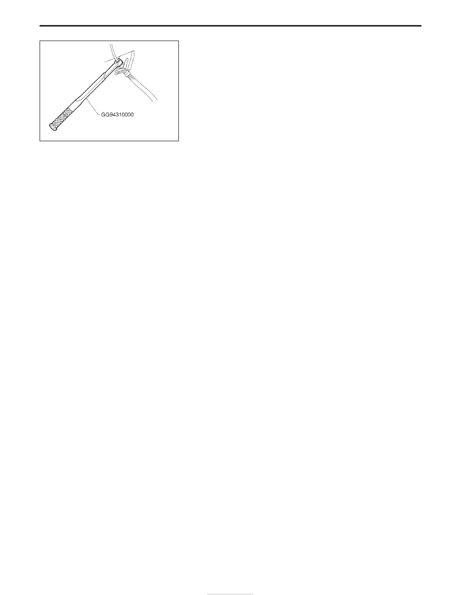
(3) Use Tool when removing or installing brake tubes.

SBR820B

PRECAUTIONS

FA-2

SPECIAL SERVICE TOOLS

*: Special tool or commercial equivalent

Tool number
Tool name

Description

ST29020001*
Gear arm puller

Removing ball joint for knuckle spindle

ST27850000
Ball joint remover

Removing tie-rod outer end

KV401021S0*
Bearing outer race
drift

q

1

ST35325000*
Drift bar

q

2

KV40102110*
Drift (A)

q

3

KV40102120*
Drift (B)

q

4

KV40102130*
Screw (A)

q

5

KV40102140*
Screw (B)

q

6

KV40102150*
Screw (C)

Installing wheel bearing outer race

KV40105400
Wheel bearing lock
nut wrench

Removing or installing wheel bearing lock nut

GG94310000*
Flare nut torque
wrench

Removing and installing brake piping

PREPARATION

FA-3

YFA003

FRONT AXLE AND FRONT SUSPENSION

FA-4

Front Axle and Front Suspension Parts

I

Check front axle and front suspension parts for looseness,
cracks, wear or other damage.

(1) Shake each front wheel.
(2) Make sure that cotter pin is inserted.
(3) Retighten all nuts and bolts to the specified torque.

: Refer to “FRONT SUSPENSION”, FA-29.

(4) Check front axle and front suspension parts for wear, cracks or

other damage.

I

Check shock absorber for oil leakage or other damage.

I

Check suspension ball joints for grease leakage and dust cov-
ers for cracks or other damage.

I

Check ball joint for vertical end play.

Upper ball joint:

1.6 mm (0.063 in) or less

(1) Jack up front of vehicle and set the stands.
(2) Clamp dial indicator onto transverse link and place indicator tip

on lower edge of brake caliper.

(3) Make sure front wheels are straight and brake pedal is

depressed.

(4) Place a pry bar between transverse link and inner rim of road

wheel.

(5) While pushing and releasing pry bar, observe maximum dial

indicator value.

(6) If ball joint movement is beyond specifications, remove and

recheck it.

SMA525A

SFA240

SMA241

SFA303A

CHECK AND ADJUSTMENT

FA-5


Content   ..  277  278  279  280   ..