Nissan Terrano model r20 series 2004. Manual - part 277


  Index      Nissan     Nissan Terrano model r20 series 2004 - Service and Repair Manual


Search            


Content   ..  275  276  277  278   ..


Nissan Terrano model r20 series 2004. Manual - part 277


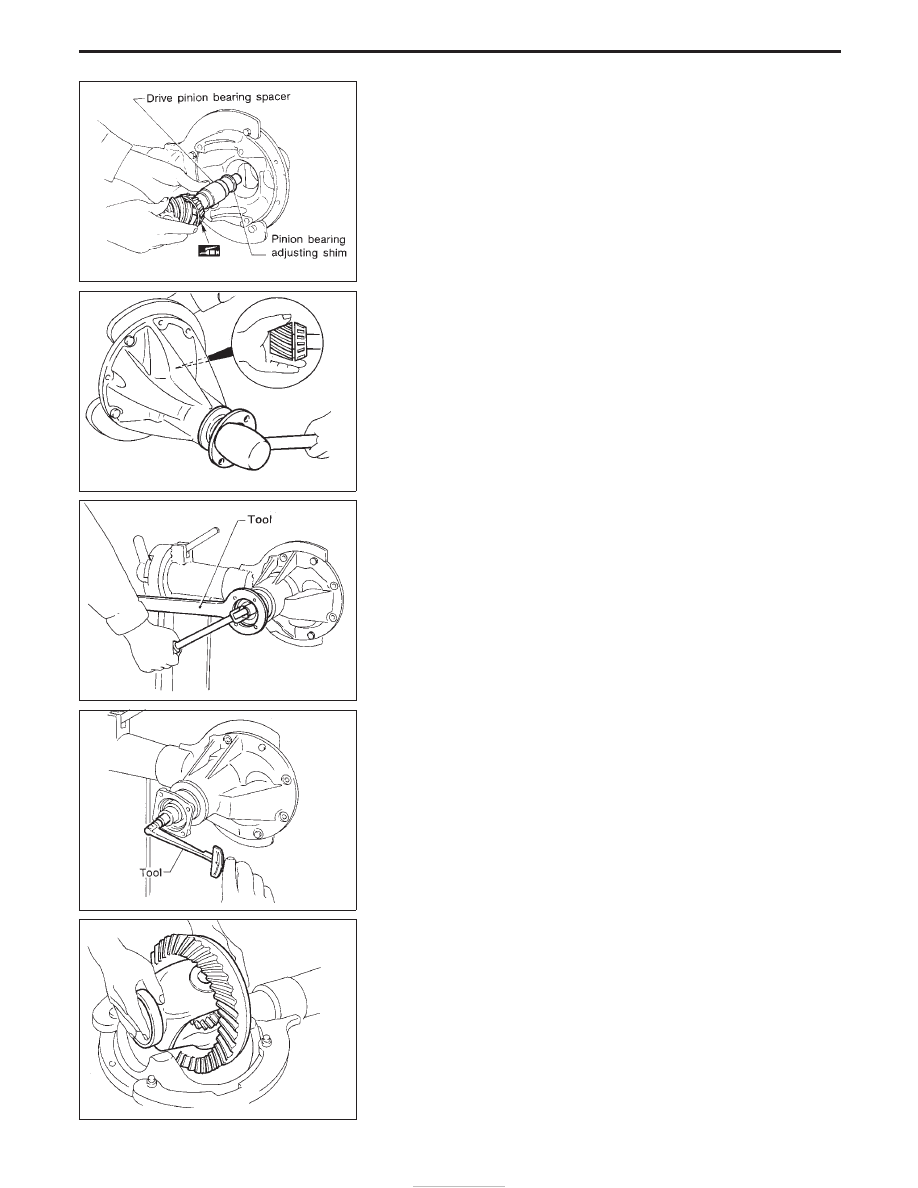
6. Install drive pinion bearing spacer, pinion bearing adjusting

shim and drive pinion in gear carrier.

7. Insert companion flange into drive pinion by tapping the com-

panion flange with a soft hammer.

8. Tighten pinion nut to specified torque.
The threaded portion of drive pinion and pinion nut should be
free from oil or grease.

Tool number:

KV38104700

9. Turn drive pinion in both directions several times, and measure

pinion bearing preload.

Tool number:

ST3127S000

Pinion bearing preload:

1.1 - 1.6 N

m (11.2 - 16.3 kg-cm, 9.7 - 14.1 in-lb)

10. Install differential case assembly with side bearing outer races

into gear carrier.

SPD712

SPD697

SPD040

SPD149

PD383

ASSEMBLY (C200)

Differential Carrier (Cont’d)

PD-54

11. Position side bearing on gear carrier with threads properly

engaged; screw in adjusters lightly at this stage of assembly.

Tool number:

ST32580000

12. Align mark on bearing cap with that on gear carrier and install

bearing cap on gear carrier.

I

Do not tighten at this point to allow further tightening of side
bearing adjusters.

13. Tighten both right and left side bearing adjusters alternately and

measure ring gear backlash and total preload at the same time.
Adjust right and left side bearing adjusters by tightening them
alternately so that proper ring gear backlash and total preload
can be obtained.

Ring gear-to-drive pinion backlash:

0.10 - 0.20 mm (0.0039 - 0.0079 in)

I

When checking preload, turn drive pinion in both direc-
tions several times to set bearing rollers.

Tool number:

ST3127S000

The total pinion bearing preload value with the differential case
assembly should be in accordance with the same value measured
without the differential case assembly. (See point 9.)
The relationship between both is:

Pinion bearing preload

With differential case assembly

Without differential case assembly

kg-cm

N

m

kg-cm

N

m

14

1.4

17 - 23

1.7 - 2.3

15

1.5

18 - 24

1.8 - 2.4

16

1.6

19 - 25

1.9 - 2.5

17

1.7

20 - 26

2.0 - 2.6

SPD684

SPD265

SPD246

SPD149

ASSEMBLY (C200)

Differential Carrier (Cont’d)

PD-55

14. Tighten side bearing cap bolts.

: 88 - 98 N

m (9.0 - 9.9 kg-m, 65 - 72 ft-lb)

15. Install side lock finger in place to prevent rotation during opera-

tion.

16. Check runout of ring gear with a dial indicator.

Runout limit:

0.08 mm (0.0031 in)

I

If backlash varies excessively in different places, the variance
may have resulted from foreign matter caught between the ring
gear and the differential case.

I

If the backlash varies greatly when the runout of the ring gear
is within a specified range, the hypoid gear set or differential
case should be replaced.

17. Check tooth contact. (Refer to PD-49.)

SPD698

SPD247

ASSEMBLY (C200)

Differential Carrier (Cont’d)

PD-56

Propeller Shaft

GENERAL SPECIFICATIONS

Unit: mm (in)

MODEL

ALL

H/T

WAGON

Portion

Front

Rear

Propeller shaft
model

0F71H

2S80B

Number of joints

2

Coupling
method with
transmission

Flange type

Sleeve type

Types of journal
bearings

Solid type (dis-
assembly type)

Solid type

Shaft length
(Spider to spi-
der)

mm (in)

569 (22.40)

750 (29.53)

950 (37.40)

Shaft outer
diameter mm (in)

65 (2.56)

65 (2.56)

INSPECTION AND ADJUSTMENT

Front propeller shaft

Unit: mm (in)

Propeller shaft model

0F71H

Journal axial play limit

0.02 (0.0008)

Propeller shaft runout limit

0.6 (0.024)

Measuring point A

L/2

YPD011

Rear propeller shaft

Unit: mm (in)

Propeller shaft model

2S80B

Journal axial play limit

0.02 (0.0008)

Propeller shaft runout limit

0.6 (0.024)

Measuring point A

L/2

YPD012

Available snap rings

0F71H models

Unit: mm (in)

Thickness mm (in)

Part number

1.25 (0.0492)

37150-2X800

1.30 (0.0512)

37149-2X800

1.35 (0.0531)

37148-2X800

1.40 (0.0551)

37147-2X800

1.45 (0.0571)

37146-2X800

2S80B models

Thickness mm (in)

Part number

1.45 (0.0571)

37146-7F000

1.50 (0.0591)

37147-7F000

1.55 (0.0610)

37148-7F000

1.60 (0.0630)

37149-7F000

1.65 (0.0650)

37150-7F000

1.70 (0.0669)

37151-7F000

1.75 (0.0689)

37152-7F000

SERVICE DATA AND SPECIFICATIONS (SDS)

PD-57


Content   ..  275  276  277  278   ..