Nissan Terrano model r20 series 2004. Manual - part 274


  Index      Nissan     Nissan Terrano model r20 series 2004 - Service and Repair Manual


Search            


Content   ..  272  273  274  275   ..


Nissan Terrano model r20 series 2004. Manual - part 274


Ring Gear and Drive Pinion

Check gear teeth for scoring, cracking or chipping.
If any damaged part is evident, replace ring gear and drive pinion
as a set (hypoid gear set).

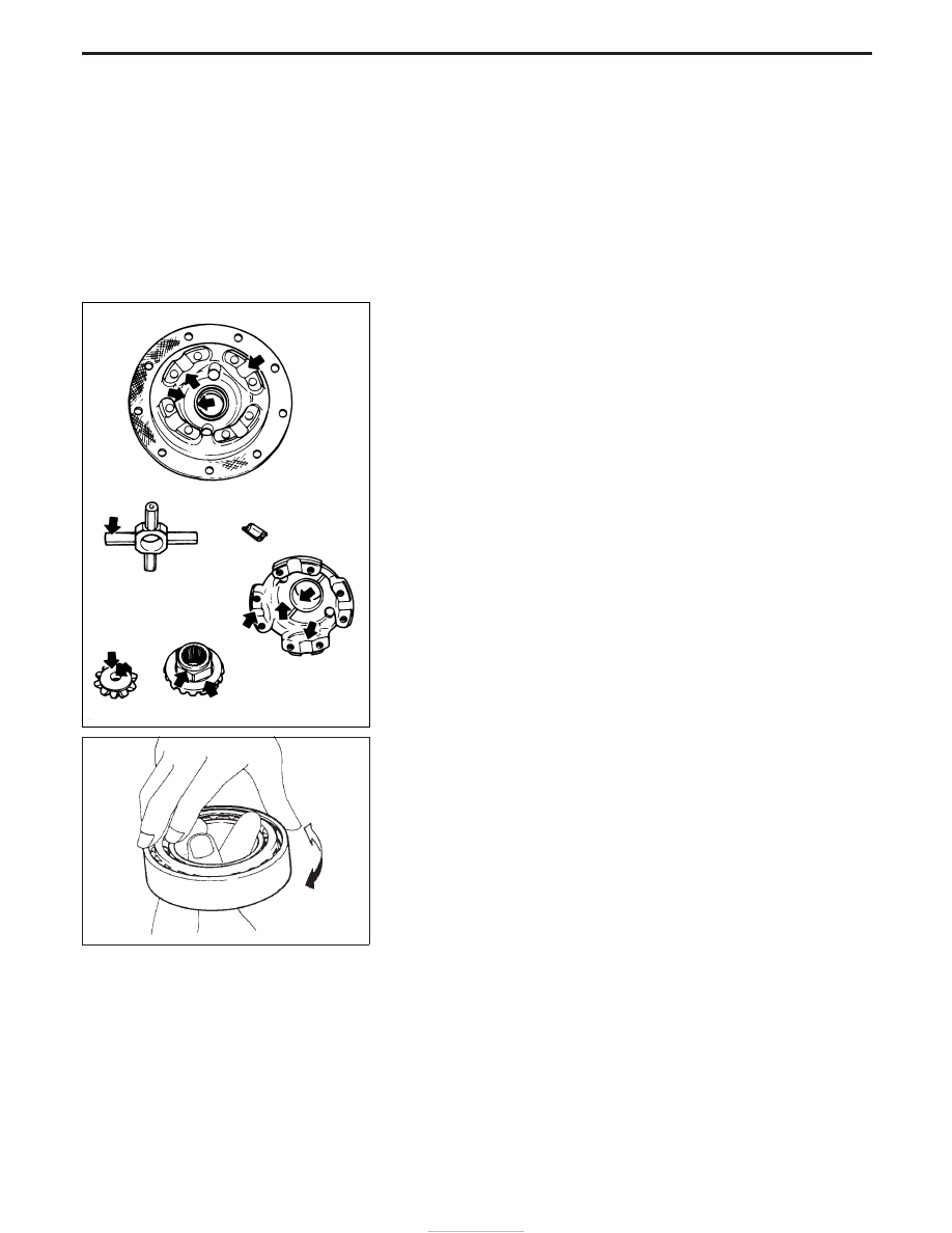
Differential Case Assembly

Check mating surfaces of differential case, side gears, pinion mate
gears, pinion mate shaft, and thrust washers.

Bearing

1. Thoroughly clean bearing.
2. Check bearings for wear, scratches, pitting or flaking.

Check tapered roller bearing for smooth rotation. If damaged,
replace outer race and inner cone as a set.

EPD009

SPD715

INSPECTION (C200)

PD-42

CAUTION:

Do not run engine when one rear wheel is off the ground.

Preparation for Disassembly

CHECKING DIFFERENTIAL TORQUE

Measure differential torque with Tool.
If it is not within the specifications, inspect components of limited
slip differential.

Differential torque:

353 - 392 N

m (36 - 40 kg-m, 260 - 289 ft-lb)

Assembly:

KV38105250

Tool number:

q

A

KV38105210

q

B

KV38105220

YPD025

SPD415

LIMITED SLIP DIFFERENTIAL (C200)

PD-43

Disassembly

1. Spread out lock straps.
2. Remove couple bolts using a press.

Tool number: ST33081000

3. Separate differential case A and B.

Draw out component parts (discs and plates, etc.)

Put marks on gears and pressure rings so that they can be
reinstalled in their original positions from which they were
removed.

Inspection

CONTACT SURFACES

1. Clean the disassembled parts in suitable solvent and blow dry

with compressed air.

2. If following surfaces are found with burrs or scratches, smooth

with oil stone.

q

1

Differential case B

q

2

Differential case A

q

3

Side gear

q

4

Pinion mate gear

q

5

Pinion mate shaft

q

6

Friction plate guide

DISC AND PLATE

1. Clean the discs and plates in suitable solvent and blow dry with

compressed air.

2. Inspect discs and plates for wear, nicks and burrs.

3. To make sure that friction disc or plate is not distorted, place it

on a surface plate and rotate it by hand with indicating finger
of dial gauge resting against disc or plate surface. Check the
warpage.

Allowable warpage:

0.05 - 0.15 mm (0.0020 - 0.0059 in)

If it exceeds limit, replace with a new plate to eliminate possi-
bility of clutch slippage or sticking.

SPD276

EPD010

SPD279

LIMITED SLIP DIFFERENTIAL (C200)

PD-44

4. Measure frictional surfaces and projected portions of friction

disc, friction plate and spring plate.

If any part has worn beyond the wear limit, replace it with a new
one that is the same thickness as the projected portion.

Wear limit:

0.1 mm (0.004 in) or less

Adjustment

FRICTION DISC AND FRICTION PLATE END PLAY

End play of friction disc and friction plate can be calculated by using
the following equation and should be adjusted within the following
range.
Adjustment can be made by selecting friction disc having two dif-
ferent thicknesses.

End play E:

0.05 - 0.15 mm (0.0020 - 0.0059 in)

E = A − (B + C)

A:

Length of differential case contact surface to differential
case inner bottom.

B:

Total thickness of friction discs, friction plates, spring disc
and spring plate in differential case on one side.

C:

Length of differential case contact surface to back side of
side gear.

1. Measure values of “A”.

Standard length A:

49.50 - 49.55 mm (1.9488 - 1.9508 in)

SPD403

SPD761

SPD417

LIMITED SLIP DIFFERENTIAL (C200)

Inspection (Cont’d)

PD-45


Content   ..  272  273  274  275   ..