Index Nissan Nissan Terrano model r20 series 2004 - Service and Repair Manual
Search
Content .. 185 186 187 188 ..
Nissan Terrano model r20 series 2004. Manual - part 187
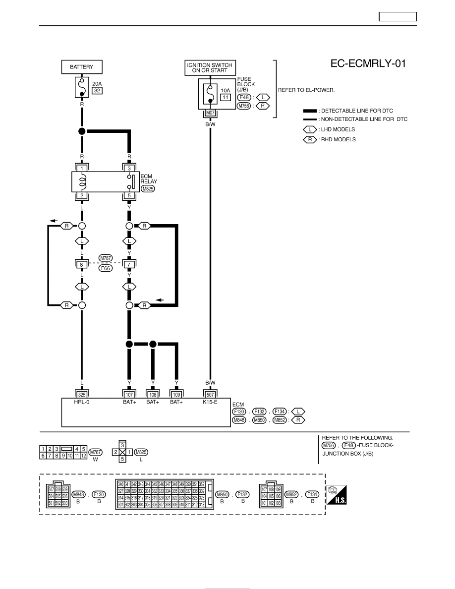
Wiring Diagram
YEC687A
DTC P1620 ECM RLY
TD27Ti
EC-470