Nissan Terrano model r20 series 2004. Manual - part 186
Diagnostic Procedure
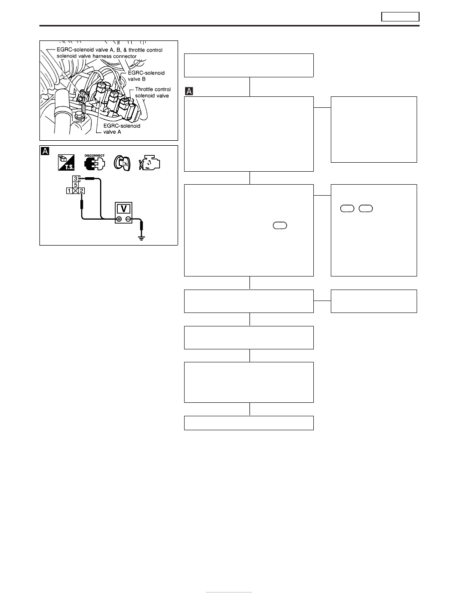
INSPECTION START
(Air conditioner relay signal circuit)
CHECK POWER SUPPLY.
1. Turn ignition switch to “LOCK” position.
2. Disconnect air conditioner relay har-
ness connector.
3. Check voltage between air conditioner
relay connector terminal
q
2
,
q
3
and
engine ground.
Voltage: Battery voltage
OK
E
NG
Check the following:
I
10A fuse
I
Harness for open or
short between fuse block
and A/C relay
If NG, replace or repair the
parts attached.
CHECK INPUT SIGNAL CIRCUIT.
1. Turn ignition switch to “LOCK” position.
2. Disconnect ECM harness connector.
3.Check harness continuity between ECM
harness connector terminal
204
and air
conditioner relay harness connector ter-
minal
q
1
. Refer to wiring diagram.
Continuity should exist.
If OK, check harness for short-
circuit.
OK
E
NG
Check the following:
I
Harness connectors
M812
,
F120
(LHD mod-
els)
I
Harness for open or
short-circuit between
ECM and air conditioner
relay.
If NG, repair harness or
connectors.
CHECK AIR CONDITIONER RELAY.
Refer to HA section for inspection.
OK
E
NG
Replace air conditioner
relay.
Disconnect and reconnect harness
connectors in the circuit. Then retest.
Trouble is not fixed
Check ECM pin terminals for damage and
check the connection of ECM harness
connector. Reconnect ECM harness con-
nector and retest.
INSPECTION END
NEF512
PBIB0185E
H
H
H
H
H
H
DTC P1530 AIR CONDITIONER RLY
TD27Ti
EC-466