Nissan Terrano model r20 series 2004. Manual - part 176


  Index      Nissan     Nissan Terrano model r20 series 2004 - Service and Repair Manual


Search            


Content   ..  174  175  176  177   ..


Nissan Terrano model r20 series 2004. Manual - part 176


Component Inspection

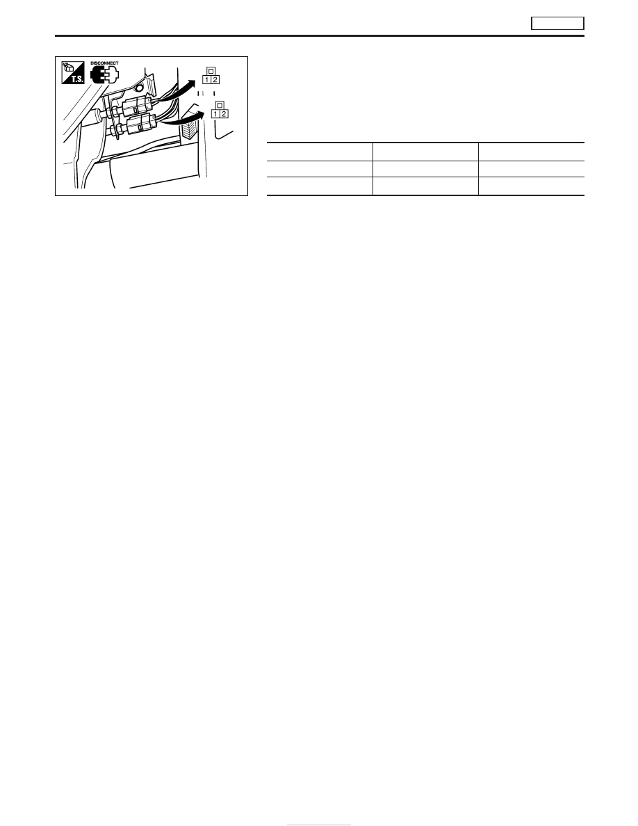
STOP LAMP SWITCH AND BRAKE SWITCH 2

1. Turn ignition switch to “LOCK” position.
2. Disconnect switch connectors.
3. Check continuity between terminals

q

1

and

q

2

.

Continuity:

Brake pedal

Stop lamp switch

Brake switch 2

Released

No

No

Depressed

Yes

Yes

If NG, replace stop lamp switch or brake switch.

MEC968D

DTC P0571 BRAKE SW

TD27Ti

EC-426

Component Description

Malfunction Indicator (MI) is located on the instrument panel. When the ignition switch is turned ON without
engine running, MI will light up. This is a bulb check. When the engine is started, MI should go off. If MI remains
on, the on board diagnostic system has detected an engine system malfunction.

On Board Diagnosis Logic

DTC No.

Trouble diagnosis name

DTC detecting condition

Possible cause

P0650
0907

Malfunction indicator (MI) control cir-
cuit

I

An excessively high voltage is sent
to ECM through the MI circuit
under the condition that calls for MI
light up.

I

An excessively low voltage is sent
to ECM through the MI circuit
under the condition that calls for MI
not to light up.

I

Harness or connectors
(MI circuit is open or shorted.)

I

MI

DTC Confirmation Procedure

NOTE:
If

“DTC

Confirmation

Procedure”

has

been

previously

conducted, always turn ignition switch “OFF” and wait at least
10 seconds before conducting the next test.

WITH CONSULT-II

1. Turn ignition switch “ON”.
2. Select “DATA MONITOR” mode with CONSULT-II.
3. Start engine and let it idle for 2 second.

WITHOUT CONSULT-II

1. Turn ignition switch “ON”.
2. Perform “Diagnostic Test Mode II” (Self-diagnostic results).
3. Start engine and let it idle for 2 second.
4. Perform “Diagnostic Test Mode II” (Self-diagnostic results).

SEF817Y

DTC P0650 MI

TD27Ti

EC-427

Wiring Diagram

YEC249A

DTC P0650 MI

TD27Ti

EC-428

Diagnostic Procedure

INSPECTION START

CHECK MI POWER SUPPLY.
1. Turn ignition switch “LOCK”.
2. Disconnect combination meter harness

connector.

3. Turn ignition switch “ON”.
4. Check voltage between combination

meter terminal

q

28

and ground with

CONSULT-II or tester.

Voltage: Battery voltage

OK

E

NG

Check the following.

I

Fuse block (J/B) con-
nector

F48

(LHD mod-

els)

M756

(RHD models)

I

10A fuse

I

Harness for open or
short between fuse
block (J/B) and combi-
nation meter

If NG, repair harness or
connectors.

CHECK MI OUTPUT SIGNAL CIRCUIT
FOR OPEN AND SHORT.
1. Turn ignition switch “LOCK”.
2. Disconnect ECM harness connector.
3. Check harness continuity between ECM

terminals

215

and combination meter

terminal

q

14

. Refer to Wiring Diagram.

4. Also check harness for short to ground

and short to power.

Continuity should exist.

OK

E

NG

Repair harness or connec-
tors.

CHECK COMBINATION METER.
1. Turn ignition switch “LOCK”.
2. Disconnect combination meter harness

connector.

3. Check continuity under the following

conditions.

OK

E

NG

Replace combination
meter. Refer to EL section.

Disconnect and reconnect harness con-
nectors in the circuits. Then retest.

Trouble is not fixed.

Check ECM pin terminals for damage and
check the connection of ECM harness
connector. Reconnect ECM harness con-
nector and retest.

INSPECTION END

CONDITION

Terminal No.

(Polarity)

Continuity

1

q

28

(+) -

q

14

(−)

Should not

exist.

2

q

28

(−) -

q

14

(+)

Should

exist.

YEC239A

YEC240A

YEC241A

H

H

H

H

H

H

DTC P0650 MI

TD27Ti

EC-429


Content   ..  174  175  176  177   ..