Nissan Terrano model r20 series 2004. Manual - part 175
Diagnostic Procedure
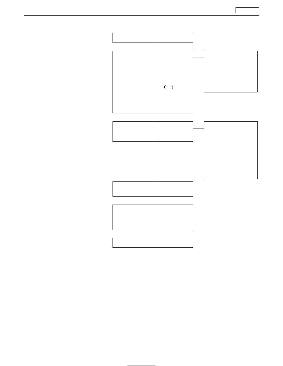
INSPECTION START
CHECK INPUT SIGNAL CIRCUIT.
1. Turn ignition switch to “LOCK” position.
2. Disconnect ECM harness connector
and combination meter harness con-
nector.
3. Check harness continuity between
ECM connector terminal
417
and
combination meter connector terminal
q
26
. Refer to wiring diagram.
Continuity should exist.
If OK, check harness for short-circuit.
OK
E
NG
Check the following:
I
Harness for open or
short-circuit between
ECM and combination
meter
If NG, repair harness or
connectors.
CHECK SPEEDOMETER FUNCTION.
Make sure that speedometer functions
properly.
OK
E
NG
Check the following:
I
Harness for open or
short-circuit between
combination meter and
vehicle speed sensor
If NG, repair harness or
connectors.
Check vehicle speed sen-
sor and its circuit.
Refer to EL section.
Disconnect and reconnect harness con-
nectors in the circuit. Then retest.
Trouble is not fixed.
Check ECM pin terminals for damage and
check the connection of ECM harness
connector. Reconnect ECM harness con-
nector and retest.
INSPECTION END
H
H
H
H
H
DTC P0500 VEHICLE SPEED SEN
TD27Ti
EC-422