Nissan Terrano model r20 series 2004. Manual - part 169


  Index      Nissan     Nissan Terrano model r20 series 2004 - Service and Repair Manual


Search            


Content   ..  167  168  169  170   ..


Nissan Terrano model r20 series 2004. Manual - part 169


Component Inspection

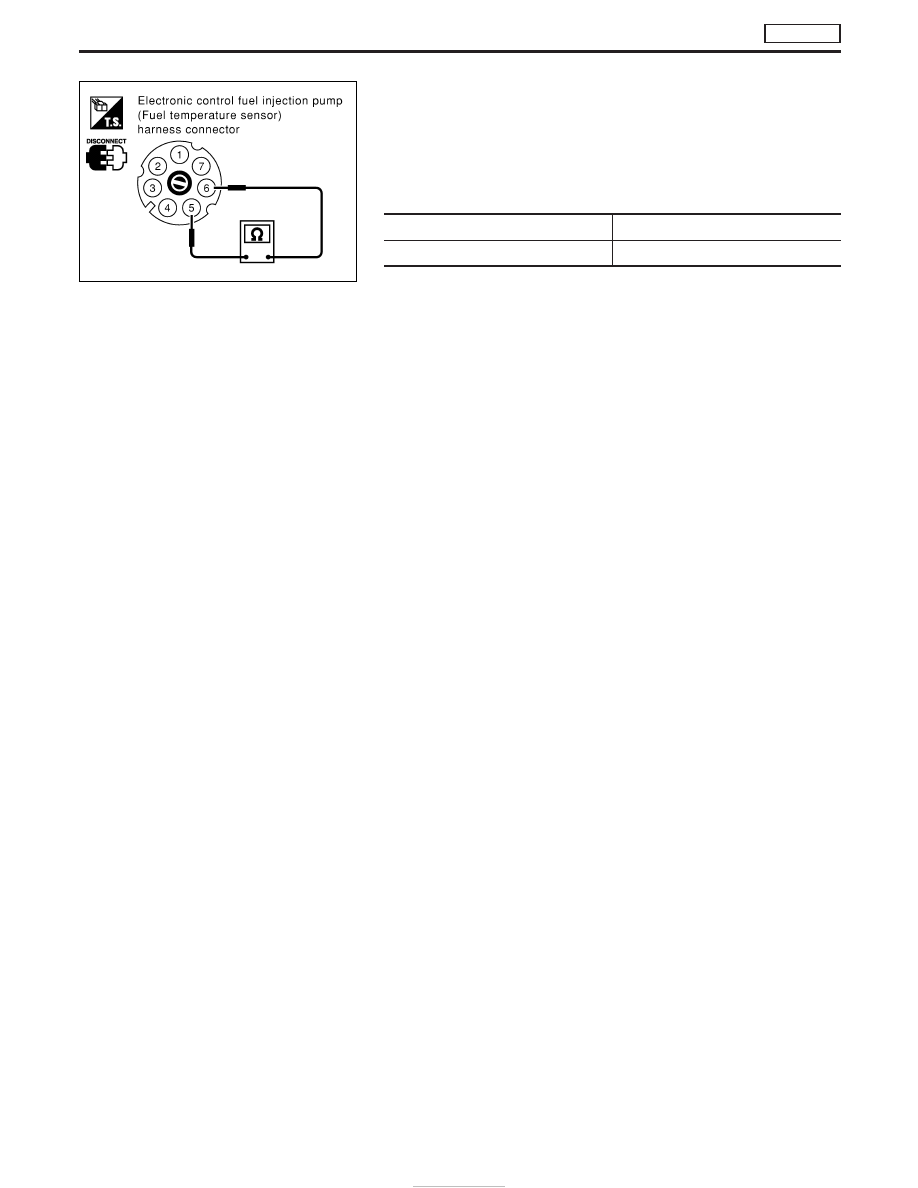
ELECTRONIC CONTROL FUEL INJECTION PUMP (FUEL
TEMPERATURE SENSOR)

Wait until fuel temperature sensor reaches room temperature.
Check resistance between electronic control fuel injection pump
(fuel temperature sensor) terminals

q

5

and

q

6

.

Temperature °C (°F)

Resistance k

25 (77)

Approximately 1.9

If NG, have the injection pump assembly serviced by an authorised
service representative.

YEC255A

DTC P0180 FUEL TEMP SENSOR

TD27Ti

EC-398

Component Description

FUEL CUT SOLENOID VALVE

When the ignition switch is off, the ECM turns the fuel cut solenoid
valve OFF (under this condition, no current flows through the fuel
cut solenoid valve), shutting off fuel supply.
When the engine is not operating due to trouble, the fuel cut sole-
noid valve may or may not be OFF even when the ignition switch
is ON.

On Board Diagnosis Logic

DTC

Malfunction is detected when ...

Check Items

(Possible Cause)

P0125
0306

I

Fuel cut solenoid valve circuit is malfunctioning.

I

Harness or connectors
(The solenoid valve circuit is open or shorted.)

I

Fuel cut solenoid valve

DTC Confirmation Procedure

NOTE:
If DTC P0115 or P0335 is displayed same time, perform trouble
diagnosis for P0115 or P0335 first.

WITH CONSULT-II

1) Turn ignition switch to “ON” position.
2) Select “DATA MONITOR” mode with CONSULT-II.
3) Start engine. (If no start, circuit is open.)
4) Warm it up sufficiently.
5) Turn ignition switch to “LOCK” position, wait at least 5 seconds.
6) Start engine and rev it up to above 1,300 rpm. Release pedal

and wait at least 3 seconds.

WITHOUT CONSULT-II

1) Start engine. (If no start, circuit is open.)
2) Warm it up sufficiently.
3) Turn ignition switch to “LOCK” position, wait at least 5 seconds.
4) Start engine and rev it up to above 1,300 rpm. Release pedal

and wait at least 3 seconds.

5) Turn ignition switch to “LOCK” position, wait at least 5 seconds

and then turn to “ON” position.

6) Perform “Diagnostic Test Mode II” (Self-diagnostic results).

SEF667S

DTC P0215 FUEL CUT S/V 1

TD27Ti

EC-399

Wiring Diagram

YEC678A

DTC P0215 FUEL CUT S/V 1

TD27Ti

EC-400

Diagnostic Procedure

INSPECTION START

CHECK POWER SUPPLY.
Check power supply.

CHECK OUTPUT SIGNAL CIRCUIT.

With CONSULT-II

1. Turn ignition switch to “ON” position.
2. Select “FUEL CUT SOL/V” in “ACTIVE

TEST” mode with CONSULT-II.

3. Touch “ON” and “OFF” alternately.
4. Check that operating sound is emitted.

Without CONSULT-II

1. Turn ignition switch to “LOCK” position.
2. Disconnect ECM harness connector

and TVC and shut-off harness connec-
tor.

3. Check harness continuity between TVC

and shut-off harness connector termi-
nal

q

8

and ECM connector terminals

202

, TVC and shut-off terminal

q

10

and ECM terminal

349

. Refer to wir-

ing diagram.
Continuity should exist.
If OK, check harness for short-circuit.

OK

E

NG

Repair harness or connec-
tors.

CHECK COMPONENT
[TVC and shut-off (Fuel cut solenoid
valve)].
Refer to “COMPONENT INSPECTION” on
page EC-402.

OK

E

NG

Replace [TVC and shut-off
(fuel cut solenoid valve)].

Disconnect and reconnect harness con-
nectors in the circuit. Then retest.

Trouble is not fixed.

Check ECM pin terminals for damage and
check the connection of ECM harness
connector. Reconnect ECM harness con-
nector and retest.

INSPECTION END

YEC256A

H

H

H

H

H

H

DTC P0215 FUEL CUT S/V 1

TD27Ti

EC-401


Content   ..  167  168  169  170   ..