Nissan Terrano model r20 series 2004. Manual - part 161
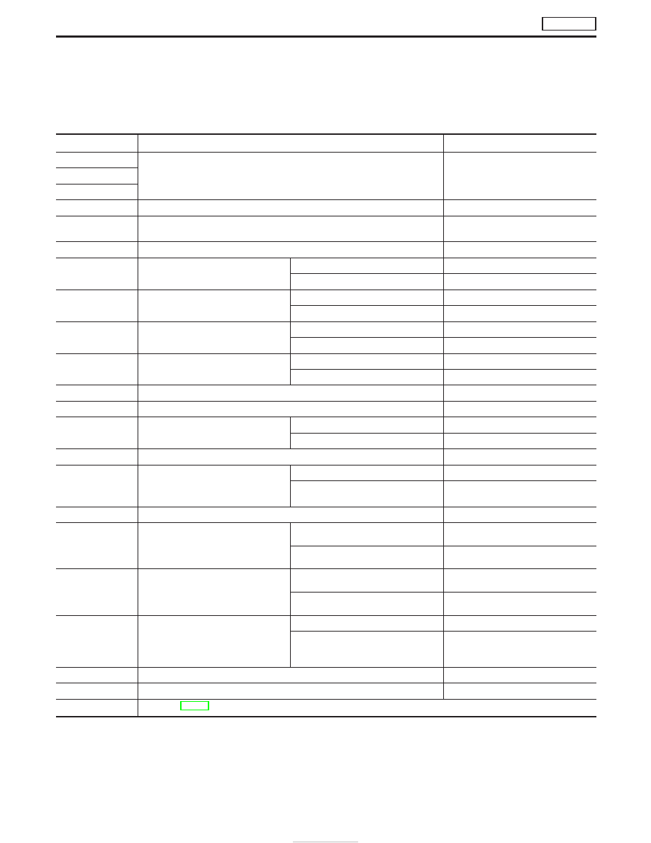
CONSULT-II Reference Value in Data Monitor
Mode
Remarks:
I
Specification data are reference values.
I
Specification data are output/input values which are detected or supplied by the ECM at the connector.
* Specification data may not be directly related to their components signals/values/operations.
MONITOR ITEM
CONDITION
SPECIFICATION
CKPS
⋅
RPM (TDC)
I
Tachometer: Connect
I
Run engine and compare tachometer indication with the CONSULT-II value.
Almost the same speed as the CON-
SULT-II value.
CKPS
⋅
RPM (REF)
CMPS
⋅
RPM-PUMP
COOLAN TEMP/S
I
Engine: After warming up
More than 70°C (158°F)
VHCL SPEED SE
I
Turn drive wheels and compare speedometer indication with the CONSULT-II
value
Almost the same speed as
the CONSULT-II value
FUEL TEMP SEN
I
Engine: After warming up
More than 40°C (104°F)
ACCEL POS SEN
I
Ignition switch: ON
(Engine stopped)
Accelerator pedal: release
0.40 - 0.60V
Accelerator pedal: depress
Approx. 4.0V
FULL ACCEL SW
I
Ignition switch: ON
(Engine stopped)
Accelerator pedal: depress
ON
Except above
OFF
ACCEL SW (FC)
I
Ignition switch: ON
(Engine stopped)
Accelerator pedal: release
CLOSE
Accelerator pedal: slightly open
OPEN
OFF ACCEL SW
I
Ignition switch: ON
(Engine stopped)
Accelerator pedal: release
ON
Accelerator pedal: slightly open
OFF
C/SLEEV POS/S
I
Engine: After warming up, idle the engine
1.0 - 3.5V
BATTERY VOLT
I
Ignition switch: ON (Engine stopped)
11 - 14V
P/N POSI SW
I
Ignition switch: ON
Shift lever: Neutral
ON
Except above
OFF
START SIGNAL
I
Ignition switch: ON
,
START
,
ON
OFF
,
ON
,
OFF
AIR COND SIG
I
Engine: After warming up, idle the
engine
Air Conditioner switch: “OFF”
OFF
Air Conditioner switch: “ON”
(Compressor operates.)
ON
IGN SW
I
Ignition switch: ON
,
OFF
ON
,
OFF
MAS AIR/FL SE
I
Engine: After warming up
I
Air Conditioner switch: “OFF”
I
Shift lever: “N”
I
No-load
Idle
1.5 - 2.1V
2,000 rpm
2.3 - 2.9V
ACT INJ TIMG
I
Engine: After warming up
I
Air Conditioner switch: “OFF”
I
Shift lever: “N”
I
No-load
Idle
−5.0° to −9.0°
2,000 rpm
−5.0° to −18.0°
DECELER F/CUT
I
Engine: After warming up
Idle
OFF
When accelerator pedal is released
quickly with engine speed at 3,000 rpm
or more.
ON
FUEL CUT S/V
I
Ignition switch: ON
,
OFF
ON
,
OFF
AIR COND RLY
I
Air Conditioner switch: OFF
,
ON
OFF
,
ON
GLOW RLY
I
Refer to EC-412.
TROUBLE DIAGNOSES
TD27Ti
EC-366