Nissan Terrano model r20 series 2004. Manual - part 159


  Index      Nissan     Nissan Terrano model r20 series 2004 - Service and Repair Manual


Search            


Content   ..  157  158  159  160   ..


Nissan Terrano model r20 series 2004. Manual - part 159


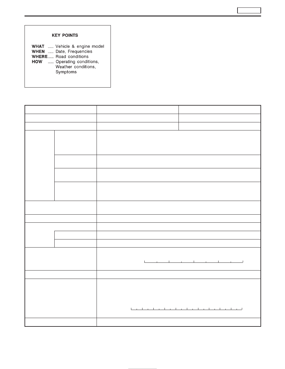
Diagnostic Worksheet

There are many operating conditions that lead to the malfunction
of engine components. A good understanding of such conditions
can make troubleshooting easier and more accurate.
In general, each customer feels differently about a problem. It is
important to fully understand the symptoms or conditions for a
customer complaint.
Utilize a diagnostic worksheet like the one shown below in order to
organize all the information for troubleshooting.

WORKSHEET SAMPLE

Customer name

MR/MS

Model & Year

VIN

Engine #

Trans.

Mileage

Incident Date

Manuf. Date

In Service Date

Symptoms

l

Startability

l

Impossible to start

l

No combustion

l

Partial combustion

l

Partial combustion when warming-up engine

l

Partial combustion when cooling down engine

l

Possible but hard to start

l

Others [

]

l

Idling

l

No fast idle

l

Unstable

l

High idle

l

Low idle

l

Others [

]

l

Driveability

l

Stumble

l

Surge

l

Knock

l

Lack of power

l

Others [

]

l

Engine stall

l

At the time of start

l

While idling

l

While accelerating

l

While decelerating

l

Just after stopping

l

While loading

Incident occurrence

l

Just after delivery

l

Recently

l

In the morning

l

At night

l

In the daytime

Frequency

l

All the time

l

Under certain conditions

l

Sometimes

Weather conditions

l

Not affected

Weather

l

Fine

l

Raining

l

Snowing

l

Others [

]

Temperature

l

Hot

l

Warm

l

Cool

l

Cold

l

Humid

°F

Engine conditions

l

Cold

l

During warm-up

l

After warm-up

Engine speed

0

2,000

4,000

6,000

8,000 rpm

Road conditions

l

In town

l

In suburbs

l

Highway

l

Off road (up/down)

Driving conditions

l

Not affected

l

At starting

l

While idling

l

At racing

l

While accelerating

l

While cruising

l

While decelerating

l

While turning (RH/LH)

Vehicle speed

0

10

20

30

40

50

60

70

80

90

100 mph

Malfunction indicator lamp

l

Turned on

l

Not turned on

SEF907L

TROUBLE DIAGNOSES

TD27Ti

EC-358

Work Flow

CHECK IN

Listen to customer complaints. (Get symptoms.)

................................................. STEP I

Check, print out or write down, and erase Diagnostic Trouble Code (DTC).

........................................... STEP II

Symptoms
collected.

No symptoms, except MI
lights up, or Malfunction
Code exists at STEP II.

Verify the symptom by driving in the condition the cus-
tomer described.

H

*1

............................................................................................. STEP III

Normal Code
(at STEP II)

Malfunction Code
(at STEP II)

Verify the DTC by performing the “DTC CONFIRMATION PROCEDURE”.

*1

........................................... STEP IV

E

Choose the appropriate action.

Malfunction Code (at STEP II or IV)

Normal Code (at both STEP II and IV)

...........................................

*2

STEP V

BASIC INSPECTION

SYMPTOM BASIS (at STEP I or III)

................................................................

E

Perform inspections
according to Symptom
Matrix Chart.

TROUBLE DIAGNOSIS FOR DTC (See TROUBLE DIAGNOSIS — INDEX,
EC-313).

STEP VI

REPAIR/REPLACE

NG

FINAL CHECK
Confirm that the incident is completely fixed by performing BASIC INSPECTION and
DTC CONFIRMATION PROCEDURE (or OVERALL FUNCTION CHECK). Then,
erase the unnecessary (already fixed) DTCs in ECM.

OK

........................................... STEP VII

CHECK OUT

*1: If the incident cannot be duplicated, refer to GI section.
*2: If the on board diagnostic system cannot be performed, check main power supply and ground circuit. Refer to

“TROUBLE DIAGNOSIS FOR POWER SUPPLY”, EC-375.

H

H

H

H

H

H

H

H

H

H

H

TROUBLE DIAGNOSES

TD27Ti

EC-359

Description for Work Flow

STEP

DESCRIPTION

STEP I

Get detailed information about the conditions and the environment when the incident/symptom occurred using the
“DIAGNOSTIC WORKSHEET” as shown on the next page.

STEP II

Before confirming the concern, check and write down (print out using CONSULT-II) the Diagnostic Trouble Code
(DTC), then erase the code. (Refer to EC-344). The DTC can be used when duplicating the incident at STEP III &
IV.
Study the relationship between the cause, specified by DTC, and the symptom described by the customer. (The
“Symptom Matrix Chart” will be useful. Refer to EC-363.)

STEP III

Try to confirm the symptom and under what conditions the incident occurs.
The “DIAGNOSTIC WORK SHEET” is useful to verify the incident. Connect CONSULT-II to the vehicle in DATA
MONITOR (AUTO TRIG) mode and check real time diagnosis results.
If the malfunction code is detected, skip STEP IV and perform STEP V.

STEP IV

Try to detect the Diagnostic Trouble Code (DTC) by driving in (or performing) the “DTC CONFIRMATION PROCE-
DURE”. Check and read the DTC by using CONSULT-II.
During the DTC verification, be sure to connect CONSULT-II to the vehicle in DATA MONITOR (AUTO TRIG) mode
and check real time diagnosis results.
In case the “DTC CONFIRMATION PROCEDURE” is not available, perform the “OVERALL FUNCTION CHECK”
instead. The DTC cannot be displayed by this check, however, this simplified “check” is an effective alternative.
The “NG” result of the “OVERALL FUNCTION CHECK” is the same as the DTC detection.

STEP V

Take the appropriate action based on the results of STEP I through IV.
If the malfunction code is indicated, proceed to TROUBLE DIAGNOSIS FOR DTC.
If the normal code is indicated, proceed to the BASIC INSPECTION. Refer to EC-361. Then perform inspections
according to the Symptom Matrix Chart. Refer to EC-363.

STEP VI

Identify where to begin diagnosis based on the relationship study between symptom and possible causes. Inspect
the system for mechanical binding, loose connectors or wiring damage using (tracing) “Harness Layouts”.
Gently shake the related connectors, components or wiring harness with CONSULT-II set in “DATA MONITOR
(AUTO TRIG)” mode.
Check the voltage of the related ECM terminals or monitor the output data from the related sensors with CON-
SULT-II. Refer to EC-369.
The “DIAGNOSTIC PROCEDURE” in EC section contains a description based on open circuit inspection. A short
circuit inspection is also required for the circuit check in the DIAGNOSTIC PROCEDURE.
Repair or replace the malfunctioning parts.

STEP VII

Once you have repaired the circuit or replaced a component, you need to run the engine in the same conditions
and circumstances which resulted in the customer’s initial complaint.
Perform the “DTC CONFIRMATION PROCEDURE” and confirm the normal code (Diagnostic trouble code No. 55)
is detected. If the incident is still detected in the final check, perform STEP VI by using a different method from the
previous one.
Before returning the vehicle to the customer, be sure to erase the unnecessary (already fixed) DTC in ECM. (Refer
to EC-344.)

TROUBLE DIAGNOSES

TD27Ti

EC-360

Basic Inspection

Precaution:
Perform Basic Inspection without electrical or mechanical
loads applied;

I

Headlamp switch is OFF,

I

Air conditioner switch is OFF,

I

Rear defogger switch is OFF,

I

Steering wheel is in the straight-ahead position, etc.

BEFORE STARTING
1. Check service records for any recent

repairs that may indicate a related
problem, or the current need for
scheduled maintenance.

2. Open engine hood and check the fol-

lowing:

I

Harness connectors for improper con-
nections

I

Vacuum hoses for splits, kinks, or
improper connections

I

Wiring for improper connections,
pinches, or cuts

3.Using priming pump, bleed air from fuel

system. Refer to “Fuel Filter Check” in
MA section.

CONNECT CONSULT-II TO THE
VEHICLE.
Connect “CONSULT-II” to the data link
connector for CONSULT-II and select
“ENGINE” from the menu.

DOES ENGINE START?

Yes

E

No

Turn ignition switch to
“LOCK” position, wait 5
seconds and then start
engine. If engine fails to
start, check diagnostic
trouble code (DTC).

Run engine for 10 minutes.

CHECK IDLE SPEED.

Read engine idle speed in “DATA
MONITOR” mode with CONSULT-II.
725 rpm ± 50 (in N position)

------------------------------------------------------------------------------------------------------------------------------------ OR ------------------------------------------------------------------------------------------------------------------------------------

Check idle speed using tachometer
tester.
725 rpm ± 50 (in N position)

(Go to

q

A

on next page.)

SEF142I

NEF463

NRS122

NEF464

SEF817Y

H

H

H

H

H

TROUBLE DIAGNOSES

TD27Ti

EC-361


Content   ..  157  158  159  160   ..