Nissan Terrano model r20 series 2004. Manual - part 158
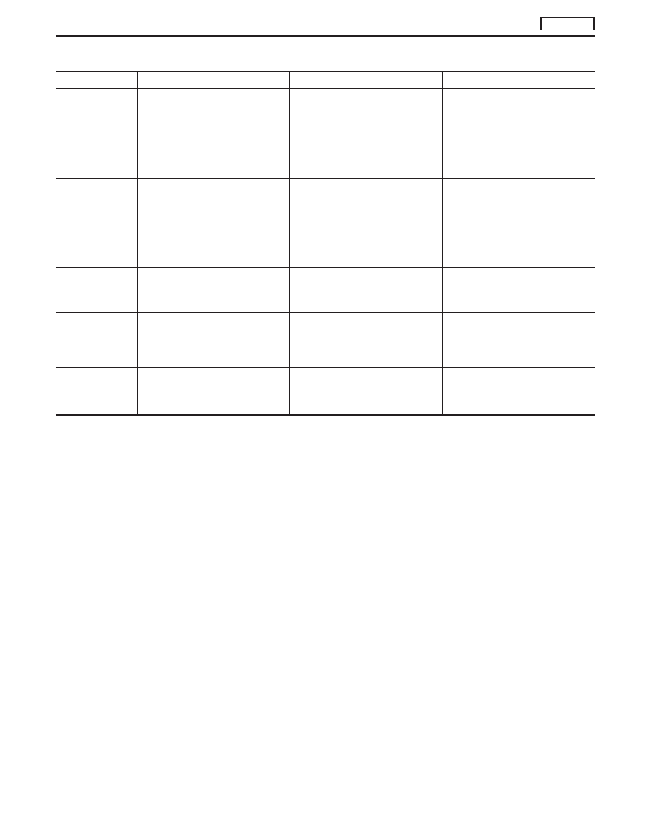
ACTIVE TEST MODE
TEST ITEM
CONDITION
JUDGEMENT
CHECK ITEM (REMEDY)
TARGET F/INJ
I
Engine: Return to the original
trouble condition.
I
Fix the target injection quantity
using CONSULT-II.
If trouble symptom disappears, see
CHECK ITEM
I
Control sleeve position sensor.
FUEL CUT SOL/V
I
Ignition switch: ON
I
Turn solenoid valve “ON” and
“OFF” with the CONSULT-II and
listen to operating sound.
Solenoid valve makes an operating
sound.
I
Harness and connector
I
Solenoid valve
EGRC SOL/V A
I
Ignition switch: ON
I
Turn solenoid valve “ON” and
“OFF” with the CONSULT-II and
listen to operating sound.
Solenoid valve makes an operating
sound.
I
Harness and connector
I
Solenoid valve
EGRC SOL/V B
I
Ignition switch: ON
I
Turn solenoid valve “ON” and
“OFF” with the CONSULT-II and
listen to operating sound.
Solenoid valve makes an operating
sound.
I
Harness and connector
I
Solenoid valve
THROT CONT
SOL/V
I
Ignition switch: ON
I
Turn solenoid valve “ON” and
“OFF” with the CONSULT-II and
listen to operating sound.
Solenoid valve makes an operating
sound.
I
Harness and connector
I
Solenoid valve
GLOW RLY
I
Ignition switch: ON (Engine
stopped)
I
Turn the glow relay “ON” and
“OFF” using CONSULT-II and
listen to operating sound.
Glow relay makes the operating
sound.
I
Harness and connector
I
Glow relay
INJ TIMING
I
Engine: Return to the original
trouble condition
I
Retard the injection timing using
CONSULT-II.
If trouble symptom disappears, see
CHECK ITEM.
I
Adjust initial injection timing
ON BOARD DIAGNOSTIC SYSTEM DESCRIPTION
TD27Ti
CONSULT-II (Cont’d)
EC-354