Nissan Terrano model r20 series 2004. Manual - part 104


  Index      Nissan     Nissan Terrano model r20 series 2004 - Service and Repair Manual


Search            


Content   ..  102  103  104  105   ..


Nissan Terrano model r20 series 2004. Manual - part 104


2

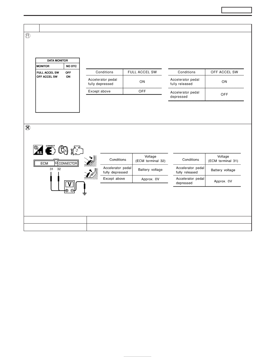
CHECK OVERALL FUNCTION-II

With CONSULT-II

1. Turn ignition switch “ON”.
2. Select “FULL ACCEL SW” and “OFF ACCEL SW” in “DATA MONITOR” mode with CONSULT-II.
3. Check “FULL ACCEL SW” and “OFF ACCEL SW” signal under the following conditions.

SEF416Y

Without CONSULT-II

1. Turn ignition switch “ON”.
2. Check voltage between ECM terminals 31, 32 and ground under the following conditions.

SEF417Y

OK or NG

OK

E

INSPECTION END

NG

E

GO TO 11.

DTC 0403 ACCEL POS SENSOR

ZD30DDTi

Diagnostic Procedure (Cont’d)

EC-138

3

CHECK ACCELERATOR POSITION SENSOR POWER SUPPLY CIRCUIT

1. Turn ignition switch “OFF”.
2. Disconnect accelerator position sensor harness connector.

MEC995D

3. Turn ignition switch “ON”.
4. Check voltage between accelerator position sensor terminal 1 and ground with CONSULT-II or tester.

SEF816Y

OK or NG

OK

E

GO TO 4.

NG

E

Repair open circuit or short to ground or short to power in harness or connectors.

DTC 0403 ACCEL POS SENSOR

ZD30DDTi

Diagnostic Procedure (Cont’d)

EC-139

4

CHECK ACCELERATOR POSITION SENSOR GROUND CIRCUIT FOR OPEN AND SHORT

1. Turn ignition switch “OFF”.
2. Loosen and retighten engine ground screw.

MEC994D

3. Check harness continuity between accelerator position sensor terminal 3 and engine ground. Refer to Wiring Diagram.

Continuity should exist.

4. Also check harness for short to ground and short to power.

OK or NG

OK

E

GO TO 5.

NG

E

Repair open circuit or short to ground or short to power in harness or connectors.

5

CHECK ACCELERATOR POSITION SENSOR INPUT SIGNAL CIRCUIT FOR OPEN AND SHORT

1. Disconnect ECM harness connector.
2. Check harness continuity between ECM terminal 23 and accelerator position sensor terminal 2. Refer to Wiring Diagram.

Continuity should exist.

3. Also check harness for short to ground and short to power.

OK or NG

OK (with CONSULT-II)

E

GO TO 6.

OK (without CONSULT-II)

E

GO TO 7.

NG

E

Repair open circuit or short to ground or short to power in harness or connectors.

DTC 0403 ACCEL POS SENSOR

ZD30DDTi

Diagnostic Procedure (Cont’d)

EC-140

6

CHECK ACCELERATOR POSITION SENSOR

With CONSULT-II

1. Reconnect all disconnected harness connectors.
2. Turn ignition switch “ON”.
3. Select “DATA MONITOR” mode with CONSULT-II.
4. Check the indication of “ACCEL POS SEN” under the following conditions.

SEF818Y

OK or NG

OK

E

GO TO 8.

NG

E

Replace accelerator pedal assembly.

7

CHECK ACCELERATOR POSITION SENSOR

Without CONSULT-II

1. Reconnect all disconnected harness connectors.
2. Turn ignition switch “ON”.
3. Check voltage between ECM terminal 23 and ground under the following conditions.

SEF407Y

OK or NG

OK

E

GO TO 9.

NG

E

Replace accelerator pedal assembly.

8

RESET ACCELERATOR POSITION SENSOR IDLE POSITION MEMORY

With CONSULT-II

1. Turn ignition switch “ON”.
2. Select “OFF ACCEL PO SIG” in “ACTIVE TEST” mode with CONSULT-II.
3. Touch “CLEAR”.

E

GO TO 10.

DTC 0403 ACCEL POS SENSOR

ZD30DDTi

Diagnostic Procedure (Cont’d)

EC-141


Content   ..  102  103  104  105   ..