Nissan Terrano model r20 series 2004. Manual - part 102


  Index      Nissan     Nissan Terrano model r20 series 2004 - Service and Repair Manual


Search            


Content   ..  100  101  102  103   ..


Nissan Terrano model r20 series 2004. Manual - part 102


Description

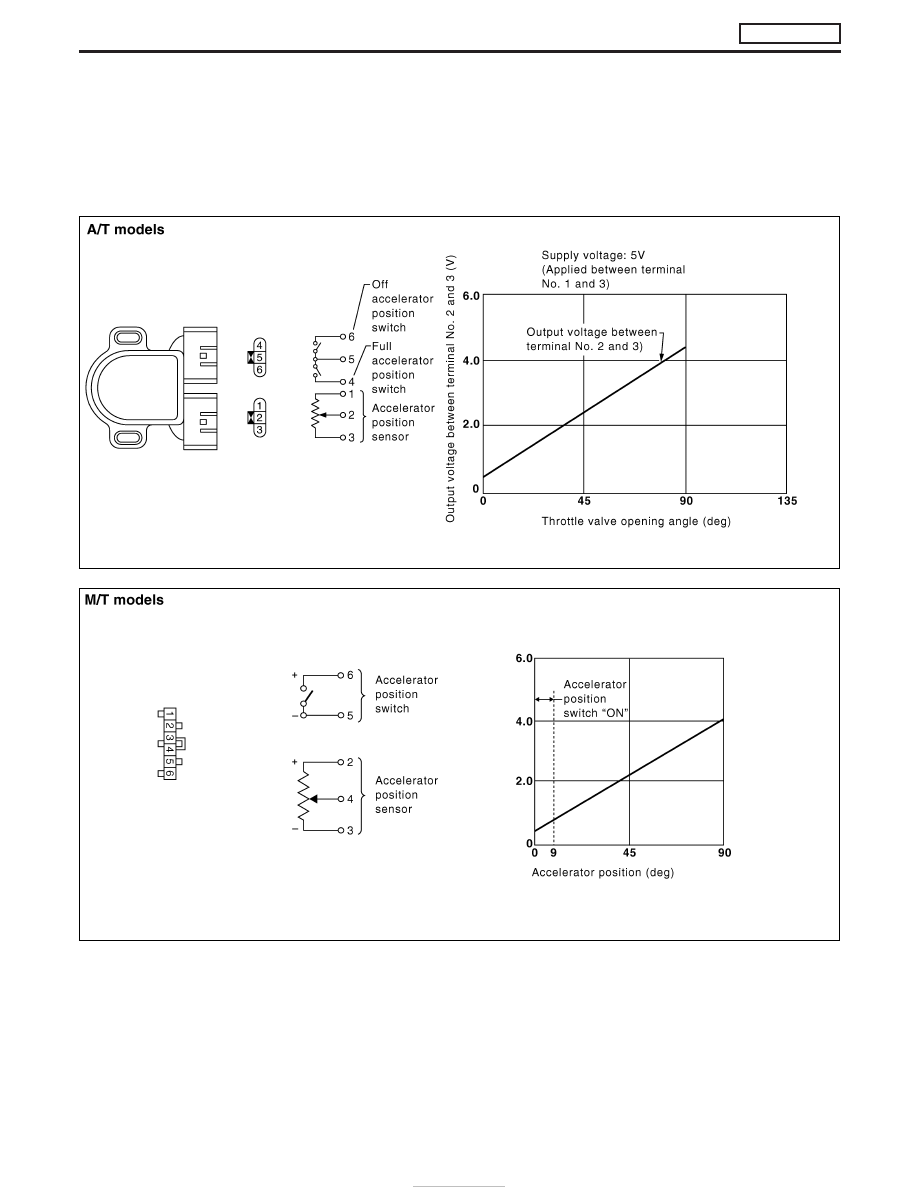
The accelerator position sensor is installed on the upper end of the accelerator pedal assembly. The sensor
detects the accelerator position and sends a signal to the ECM. The ECM uses the signal to determine the
amount of fuel to be injected.
The accelerator position switch detects Off-accelerator switch signal and Full-accelerator switch signal (A/T
models only) and send these signals to the ECM. The ECM will then determine engine idle conditions. These
signals are also used for diagnosing the accelerator position sensor.

SEF861SB

YEC703A

DTC 0403 ACCEL POS SENSOR

ZD30DDTi

EC-130

CONSULT-II Reference Value in Data Monitor
Mode

Specification data are reference values.

MONITOR ITEM

CONDITION

SPECIFICATION

ACCEL POS SEN

I

Ignition switch: ON
(Engine stopped)

Accelerator pedal: released

0.40 - 0.60V

Accelerator pedal: depressed

Approx. 4.5V

FULL ACCEL SW

I

Ignition switch: ON
(Engine stopped)

Accelerator pedal: fully depressed

ON

Except above

OFF

OFF ACCEL SW

I

Ignition switch: ON
(Engine stopped)

Accelerator pedal: fully released

ON

Accelerator pedal: slightly open

OFF

ECM Terminals and Reference Value

Specification data are reference values and are measured between each terminal and ground.

CAUTION:

Do not use ECM ground terminals when measuring input/output voltage. Doing so may damage the
ECM’s transistor. Use a ground other than ECM terminals, such as the ground.

TER-

MINAL

NO.

WIRE

COLOR

ITEM

CONDITION

DATA (DC Voltage)

23

G

Accelerator position sen-
sor

Ignition switch “ON”

Accelerator pedal fully released

0.4 - 0.6V

Ignition switch “ON”

Accelerator pedal fully depressed

Approximately 4.5V

31

L/Y

Accelerator position switch
(Idle)

Ignition switch “ON”

Accelerator pedal fully released

BATTERY VOLTAGE
(11 - 14V)

Ignition switch “ON”

Accelerator pedal depressed

Approximately 0V

32

R/L

Accelerator position switch
(Full)

Ignition switch “ON”

Accelerator pedal released

Approximately 0V

Ignition switch “ON”

Accelerator pedal fully depressed

BATTERY VOLTAGE
(11 - 14V)

48

R/B

Accelerator position sen-
sor power supply

Ignition switch “ON”

Approximately 5V

51

B/W

Accelerator position sen-
sor ground

Engine is running.

Warm-up condition
Idle speed

Approximately 0V

DTC 0403 ACCEL POS SENSOR

ZD30DDTi

EC-131

On Board Diagnosis Logic

Malfunction is detected when ...

Check Items (Possible Cause)

I

The relation between sensor and switch signal is not in the
normal range during the specified accelerator position.

I

Harness or connectors
(The sensor circuit is open or shorted.)

I

Accelerator position sensor

I

Accelerator position switch

I

Accelerator switch (F/C)

DTC Confirmation Procedure

WITH CONSULT-II

1) Turn ignition switch “ON”.
2) Select “DATA MONITOR” mode with CONSULT-II.
3) Depress and release fully accelerator pedal slowly.
4) If DTC is detected, go to “Diagnostic Procedure”, EC-144.

WITHOUT CONSULT-II

1) Turn ignition switch “ON”.
2) Depress and release fully accelerator pedal slowly.
3) Turn ignition switch “OFF”, wait at least 5 seconds and then turn

“ON”.

4) Perform “Diagnostic Test Mode II (Self-diagnostic results)” with

ECM.

5) If DTC is detected, go to “Diagnostic Procedure”, EC-144.

SEF817Y

DTC 0403 ACCEL POS SENSOR

ZD30DDTi

EC-132

Wiring Diagram

A/T MODELS

YEC689A

DTC 0403 ACCEL POS SENSOR

ZD30DDTi

EC-133


Content   ..  100  101  102  103   ..