Nissan Terrano r20e. Manual - part 428
Disassembly
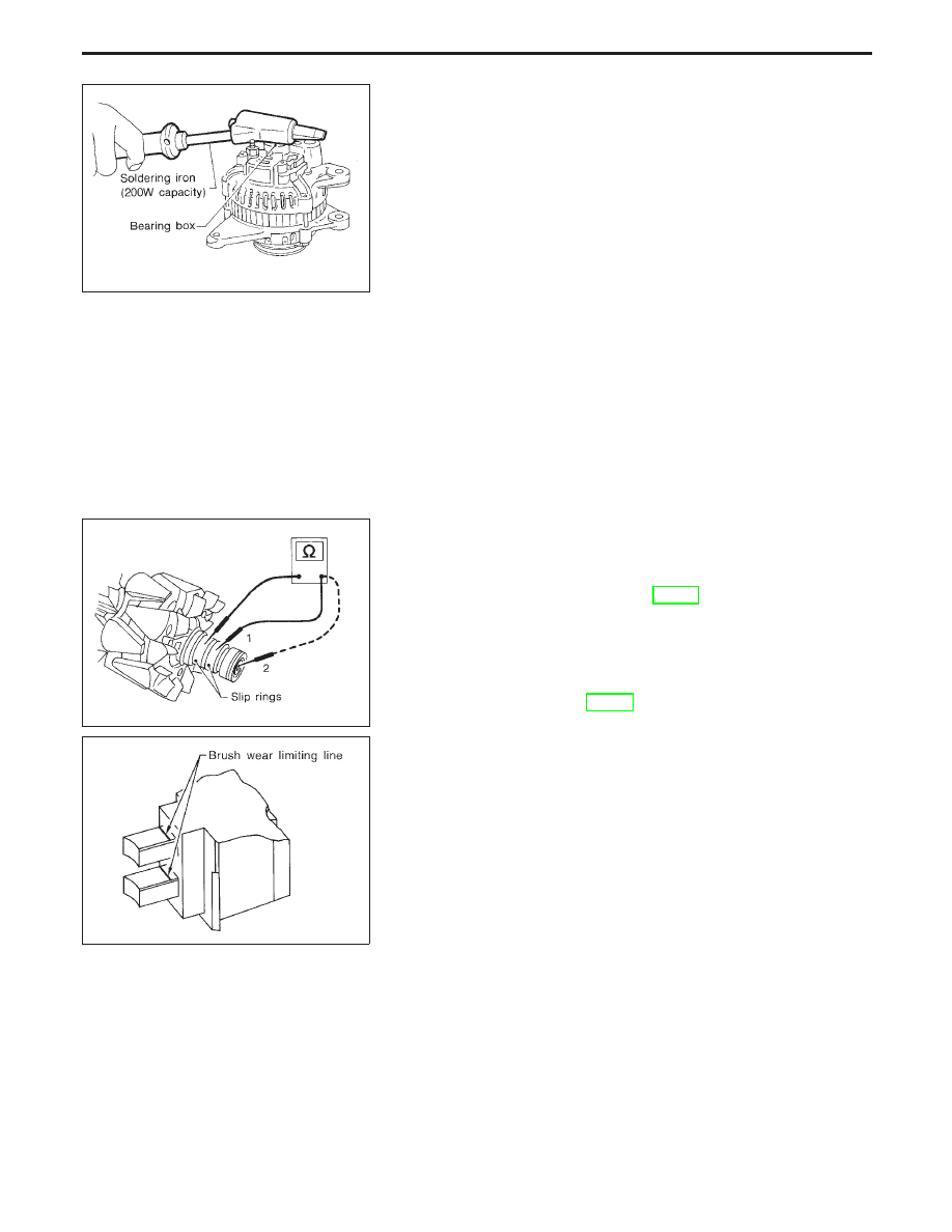
REAR COVER
CAUTION:
Rear cover may be hard to remove because a ring is used to
lock outer race of rear bearing. To facilitate removal of rear
cover, heat just bearing box section with a 200W soldering
iron.
Do not use a heat gun, as it can damage diode assembly.
REAR BEARING
CAUTION:
I
Do not reuse rear bearing after removal. Replace with a
new one.
I
Do not lubricate rear bearing outer race.
Inspection
ROTOR CHECK
1. Resistance test
Resistance: Refer to SDS (SC-30).
I
Not within the specified values ... Replace rotor.
2. Insulator test
I
Continuity exists ... Replace rotor.
3. Check slip ring for wear.
Slip ring minimum outer diameter:
Refer to SDS (SC-30).
I
Not within the specified values ... Replace rotor.
BRUSH CHECK
1. Check smooth movement of brush.
I
Not smooth ... Check brush holder and clean.
2. Check brush for wear.
I
Replace brush if it is worn down to the limit line.
SEL032Z
SEL033Z
SEL631DA
CHARGING SYSTEM
SC-28