Nissan Terrano r20e. Manual - part 399


  Index      Nissan     Nissan Terrano r20e - Service and Repair Manual


Search            


Content   ..  397  398  399  400   ..


Nissan Terrano r20e. Manual - part 399


6. Install pinion mate gears and pinion shaft to differential case B.

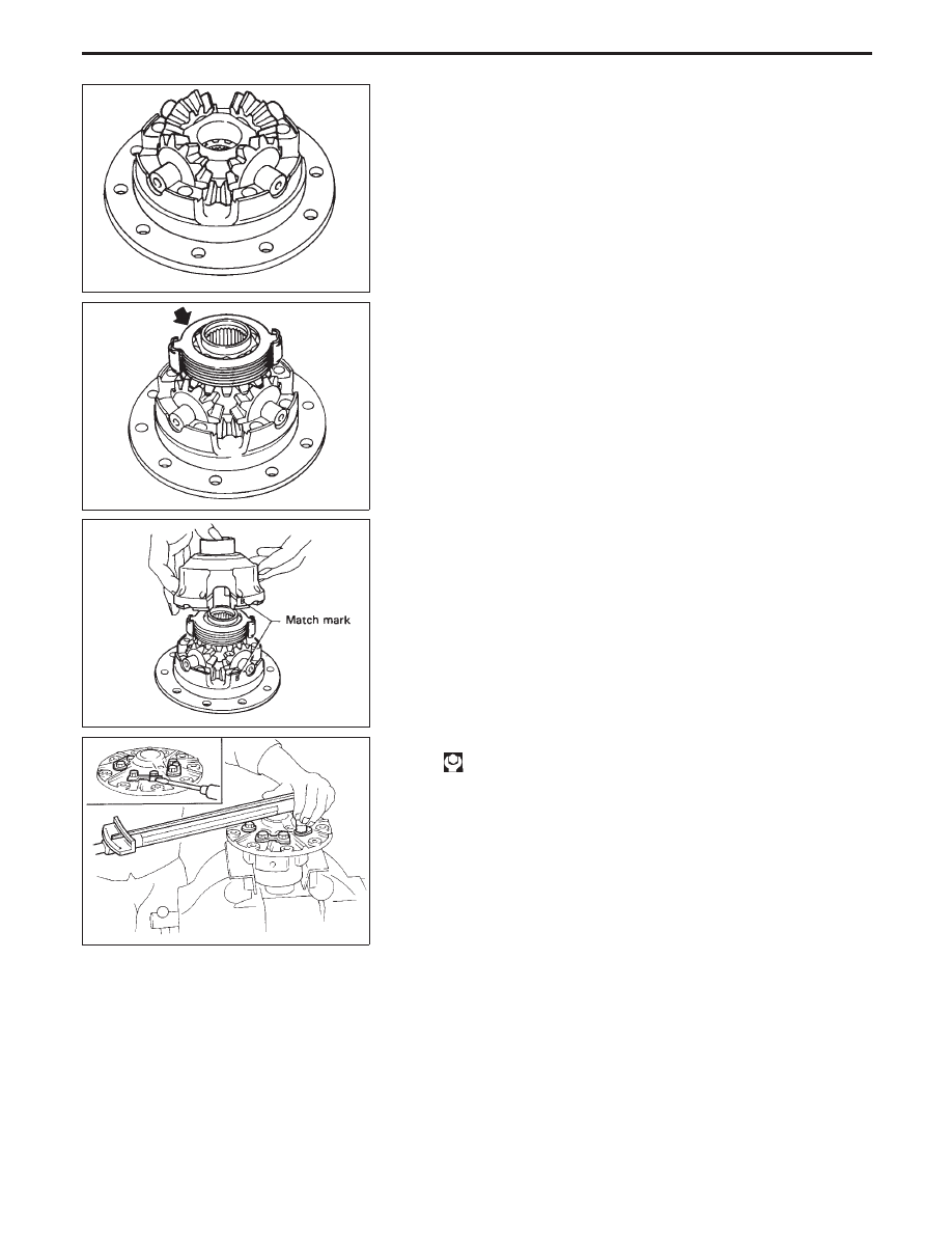
7. Install side gear to pinion mate gears.
8. Install each disc and plate.
Use same procedures as outlined in steps 1. through 4. above.

9. Install differential case A.
Position differential cases A and B by correctly aligning marks
stamped on cases.

10. Tighten differential case bolts.

: 64 - 69 N

m (6.5 - 7.0 kg-m, 47 - 51 ft-lb)

11. Place ring gear on differential case and install new lock straps

and bolts.

Tighten bolts in a criss-cross fashion, lightly tapping bolt head
with a hammer.
Then bend up lock straps to lock the bolts in place.
12. Install side bearing inner cone.
13. Check differential torque.

SPD426

SPD429

SPD430

SPD288

LIMITED SLIP DIFFERENTIAL (H233B)

Assembly (Cont’d)

PD-48

To avoid confusion while calculating bearing shims, it is absolutely
necessary to stay with the metric system. If you measure anything
in inches, the results MUST be converted to the metric system.

Drive Pinion Height

1. First prepare Tools for pinion height adjustment.

Assembly

q

1

q

2

:

ST3125500

q

1

Height Gauge (ST31251000)

q

2

Dummy Shaft (ST31181001)

q

3

Spacer [thickness: 2.50 mm (0.0984 in)]

q

4

Feeler Gauge

2. To simplify the job, make a chart, like the one below, to orga-

nize your calculations.

LETTERS

HUNDREDTHS OF

A MILLIMETER

H:

Head number

D

:

Figure marked on dummy shaft

S:

Figure marked on height gauge

N:

Measuring clearance

3. Write the following numbers down in the chart.

H: Head number

D

: Figure marked on dummy shaft

SPD758

SPD542

SPD759

ADJUSTMENT (H233B)

PD-49

S: Figure marked on height gauge

4. Place pinion rear bearing inner race and Tools on gear carrier.

5. Attach Tool (Height gauge) to gear carrier, and measure the

clearance between the height gauge tip and the dummy shaft
face.

SPD760

SPD271

SPD272

PD444

ADJUSTMENT (H233B)

Drive Pinion Height (Cont’d)

PD-50

6. Substitute these values into the equation to calculate the thick-

ness of the washer.

If values signifying H, D

and S are not given, regard them as

zero and calculate.

T (Thickness of washer) = N − [(H − D

− S) x 0.01] +

3.05

Example:

N = 0.30

H = 2

D

= −1

S = 0

T=N − [(H − D

− S) x 0.01] + 3.05

= 0.30 − [{2 − (−1) − 0} x 0.01] + 3.05

(1)

H................................................................................2

− D

.......................................................................−(−1)

3

− S.............................................................................−0

3

(2)

3

x 0.01

0.03

(3)

N...........................................................................0.30

−0.03

0.27

(4)

0.27

+3.05

3.32

T = 3.32

7. Select the proper washer. (Refer to PD-57.)
If you cannot find the desired thickness of washer, use washer
with thickness closest to the calculated value.
Example:
Calculated value ... T = 3.32 mm
Used washer ... T = 3.33 mm

ADJUSTMENT (H233B)

Drive Pinion Height (Cont’d)

PD-51


Content   ..  397  398  399  400   ..