Nissan Terrano r20e. Manual - part 400


  Index      Nissan     Nissan Terrano r20e - Service and Repair Manual


Search            


Content   ..  398  399  400  401   ..


Nissan Terrano r20e. Manual - part 400


Tooth Contact

Gear tooth contact pattern check is necessary to verify correct
relationship between ring gear and drive pinion.
Hypoid gear sets which are not positioned properly in relation to
one another may be noisy, or have short life span or both. With a
pattern check, the most desirable contact for low noise level and
long life can be assured.

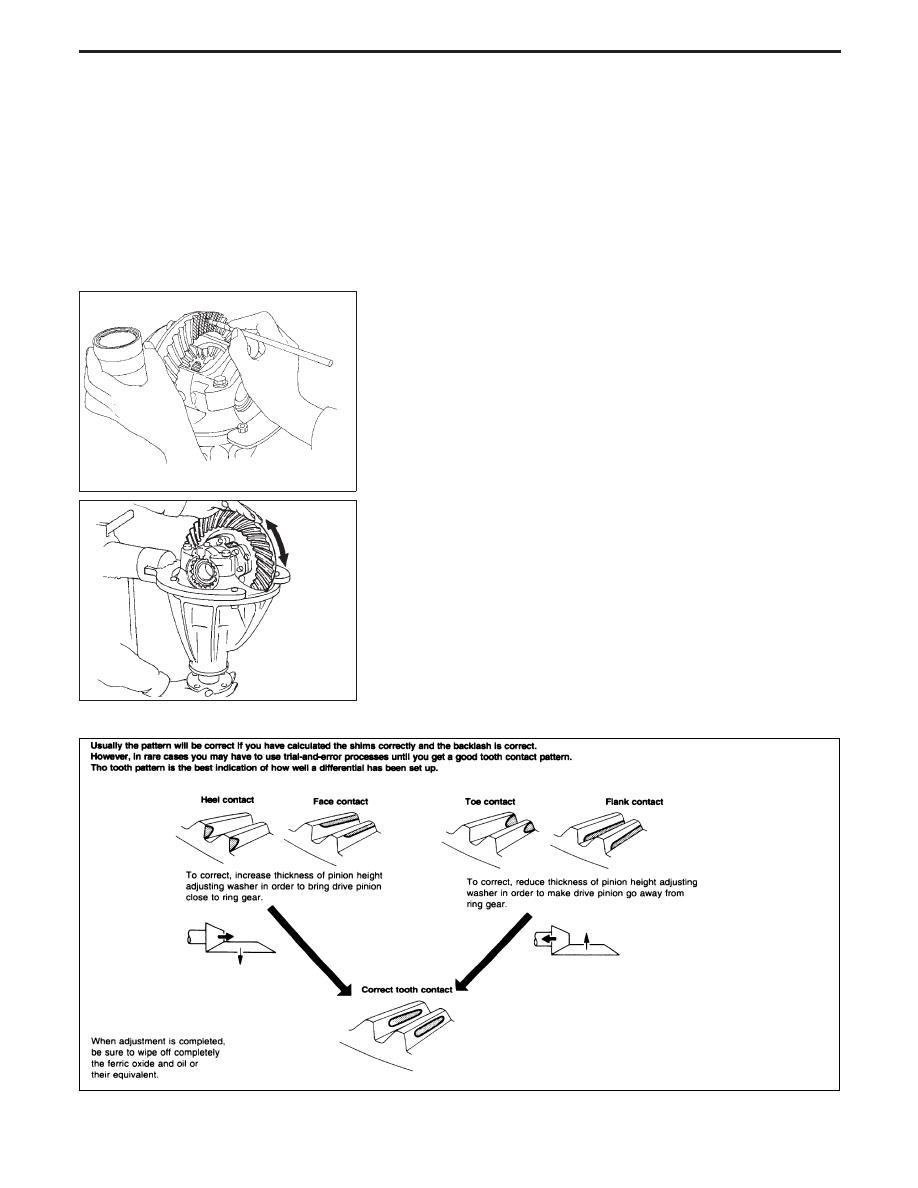
1. Thoroughly clear ring gear and dive pinion teeth.
2. Sparingly apply a mixture of powdered ferric oxide and oil or

equivalent to 3 or 4 teeth of ring gear drive side.

3. Hold companion flange steady by hand and rotate the ring gear

in both directions.

SPD005

SPD695

NPD003

ADJUSTMENT (H233B)

PD-52

Differential Carrier

1. Press-fit front and rear bearing outer races with Tools.

Tool number:

q

A

ST30611000

q

B

ST30621000

q

C

ST30613000

2. Select drive pinion height adjusting washer, referring to Adjust-

ment.

3. Install drive pinion adjusting washer in drive pinion, and press-

fit pinion rear bearing inner cone in it with press and Tool.

Tool number:

ST30901000

4. Place pinion front bearing inner cone in gear carrier.

5. Apply multi-purpose grease to cavity at sealing lips of oil seal.

Install front oil seal.

Tool number:

q

A

ST30720000

q

B

KV38102510

SPD580

SPD377

SPD581

YPD009

ASSEMBLY (H233B)

PD-53

6. Install drive pinion bearing spacer, pinion bearing adjusting

shim and drive pinion in gear carrier.

7. Insert companion flange into drive pinion by tapping the com-

panion flange with a soft hammer.

8. Tighten pinion nut to specified torque.
The threaded portion of drive pinion and pinion nut should be
free from oil or grease.

Tool number:

KV38104700

9. Turn drive pinion in both directions several times, and measure

pinion bearing preload.

Tool number:

ST3127S000

Pinion bearing preload:

1.7 - 2.5 N

m (17 - 26 kg-cm, 15 - 23 in-lb)

10. Install differential case assembly with side bearing outer races

into gear carrier.

SPD712

SPD697

SPD040

SPD149

PD383

ASSEMBLY (H233B)

Differential Carrier (Cont’d)

PD-54

11. Position side bearing on gear carrier with threads properly

engaged; screw in adjusters lightly at this stage of assembly.

Tool number:

ST32580000

12. Align mark on bearing cap with that on gear carrier and install

bearing cap on gear carrier.

I

Do not tighten at this point to allow further tightening of side
bearing adjusters.

13. Tighten both right and left side bearing adjusters alternately and

measure ring gear backlash and total preload at the same time.
Adjust right and left side bearing adjusters by tightening them
alternately so that proper ring gear backlash and total preload
can be obtained.

Ring gear-to-drive pinion backlash:

0.15 - 0.20 mm (0.0059 - 0.0079 in)

I

When checking preload, turn drive pinion in both direc-
tions several times to set bearing rollers.

Tool number:

ST3127S000

The total pinion bearing preload value with the differential case
assembly should be in accordance with the same value measured
without the differential case assembly. (See point 9.)
The relationship between both is:

Pinion bearing preload

With differential case assembly

Without differential case assembly

kg-cm

N

m

kg-cm

N

m

14

1.4

17 - 23

1.7 - 2.3

15

1.5

18 - 24

1.8 - 2.4

16

1.6

19 - 25

1.9 - 2.5

17

1.7

20 - 26

2.0 - 2.6

SPD684

SPD265

SPD246

SPD149

ASSEMBLY (H233B)

Differential Carrier (Cont’d)

PD-55


Content   ..  398  399  400  401   ..