Nissan Terrano r20e. Manual - part 398
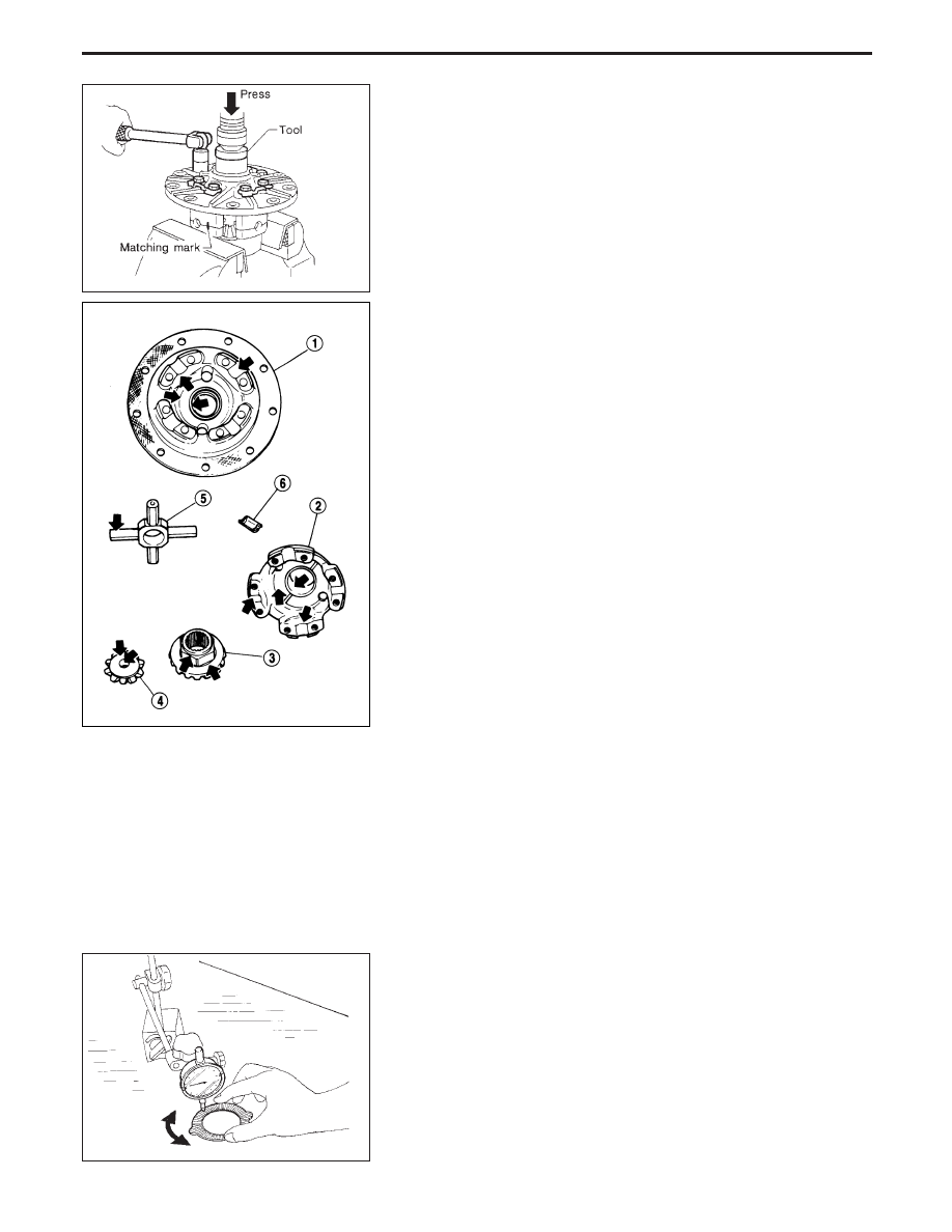
Disassembly
1. Spread out lock straps.
2. Remove couple bolts using a press.
Tool number: ST33081000
3. Separate differential case A and B.
Draw out component parts (discs and plates, etc.)
Put marks on gears and pressure rings so that they can be
reinstalled in their original positions from which they were
removed.
Inspection
CONTACT SURFACES
1. Clean the disassembled parts in suitable solvent and blow dry
with compressed air.
2. If following surfaces are found with burrs or scratches, smooth
with oil stone.
q
1
Differential case B
q
2
Differential case A
q
3
Side gear
q
4
Pinion mate gear
q
5
Pinion mate shaft
q
6
Friction plate guide
DISC AND PLATE
1. Clean the discs and plates in suitable solvent and blow dry with
compressed air.
2. Inspect discs and plates for wear, nicks and burrs.
3. To make sure that friction disc or plate is not distorted, place it
on a surface plate and rotate it by hand with indicating finger
of dial gauge resting against disc or plate surface. Check the
warpage.
Allowable warpage:
0.05 - 0.15 mm (0.0020 - 0.0059 in)
If it exceeds limit, replace with a new plate to eliminate possi-
bility of clutch slippage or sticking.
SPD276
EPD010
SPD279
LIMITED SLIP DIFFERENTIAL (H233B)
PD-44