Nissan Terrano r20e. Manual - part 390


  Index      Nissan     Nissan Terrano r20e - Service and Repair Manual


Search            


Content   ..  388  389  390  391   ..


Nissan Terrano r20e. Manual - part 390


Removal

1. Remove front propeller shaft.
2. Remove drive shaft. Refer to FA section.
3. Remove engine mounting bolts and raise up engine.
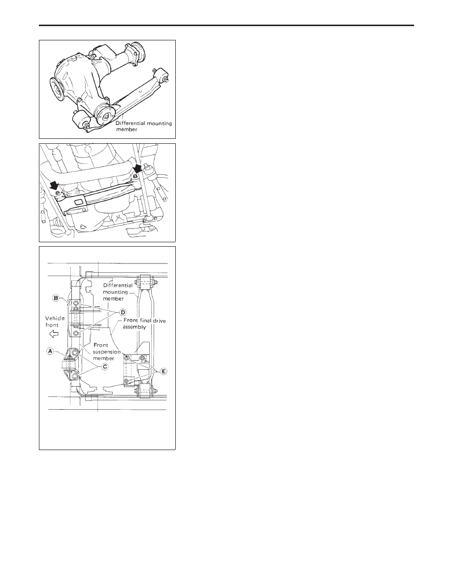
4. Remove front final drive together with differential mounting

member.

Installation

1. Install front final drive assembly together with differential

mounting member.

2. Tighten the front final drive securing bolts and nuts following the

procedures below to prevent drive train vibration.

(1) Temporarily tighten nut

q

A

.

(2) Temporarily tighten nut

q

B

.

(3) Tighten bolts

q

C

to the torque of 68 to 87 N

m (6.9 to 8.9 kg-m,

50 to 64 ft-lb).

(4) Tighten bolts

q

D

to the torque of 68 to 87 N

m (6.9 to 8.9 kg-m,

50 to 64 ft-lb).

(5) Tighten nut

q

A

to the torque of 68 to 87 N

m (6.9 to 8.9 kg-m,

50 to 64 ft-lb).

(6) Tighten nut

q

B

to the torque of 68 to 87 N

m (6.9 to 8.9 kg-m,

50 to 64 ft-lb).

(7) Tighten nuts

q

E

to the torque of 68 to 87 N

m (6.9 to 8.9 kg-m,

50 to 64 ft-lb).

3. Install drive shaft. Refer to FA section.
4. Install front propeller shaft.

SPD741

SPD742

SPD743

REMOVAL AND INSTALLATION (Front final drive — R180A)

PD-12

Removal

I

Remove propeller shaft.

Insert plug into transfer or transmission after removing pro-
peller shaft.

I

Remove axle shaft. Refer to RA section.

CAUTION:

I

Be careful not to damage spline, sleeve yoke and front oil
seal when removing propeller shaft.

Installation

I

Fill final drive with recommended gear oil.

SPD123

REMOVAL AND INSTALLATION (Rear final drive — H233B)

PD-13

YPD003

FRONT FINAL DRIVE (R180A)

PD-14

Pre-inspection

Before disassembling final drive, perform the following inspection.

I

Total preload

I

Remove the extension tube and the side flange. This measure-
ment must be performed with the extension tube and the differ-
ential flange removed.

1) Turn drive pinion in both directions several times to set bearing

rollers.

2) Check total preload with Tool.

Tool number:

ST3127S000

Total preload:

1.2 - 2.3 N

m (12 - 23 kg-cm, 8.7 - 20.0 in-lb)

I

Ring gear to drive pinion backlash
Check backlash of ring gear with a dial indicator at several
points.

Ring gear-to-drive pinion backlash:

0.13 - 0.18 mm (0.0051 - 0.0071 in)

I

Ring gear runout
Check runout of ring gear with a dial indicator.

Runout limit:

0.05 mm (0.0020 in)

I

Tooth contact
Check tooth contact (Refer to Adjustment).

Final Drive Housing

1. Using three spacers [20 mm (0.79 in)], mount final drive assem-

bly on Tool.

Tool number:

KV38100800

SPD634

SPD635

SPD636

SPD637

DISASSEMBLY (R180A)

PD-15


Content   ..  388  389  390  391   ..