Nissan Terrano r20e. Manual - part 317
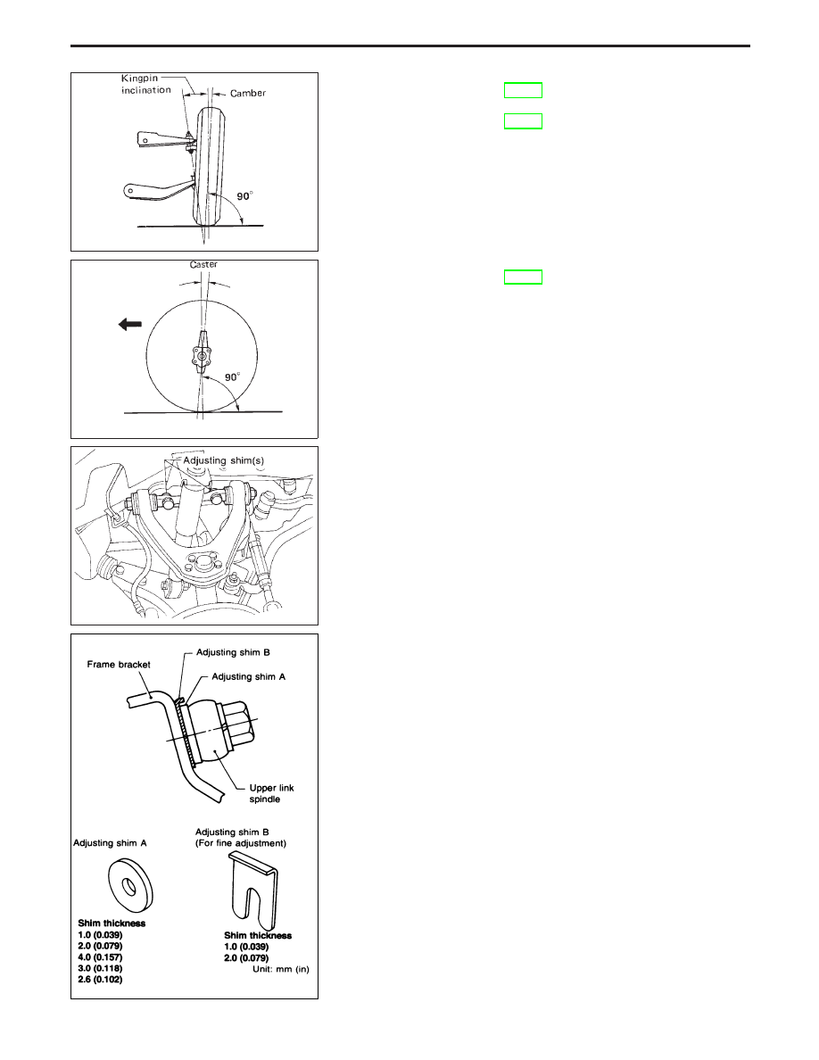
Camber (Unladen):
Refer to SDS, FA-39.
Kingpin inclination (Unladen):
Refer to SDS, FA-39.
Caster (Unladen):
Refer to SDS, FA-39.
ADJUSTMENT
Both camber and caster angles are adjusted by increasing or
decreasing the number of adjusting shims inserted between upper
link spindle and frame.
Before removing or installing adjusting shim(s), be sure to
place a jack under lower link.
Adjusting shim standard thickness:
4.0 mm (0.157 in)
I
Do not use three or more shims at one place.
I
When installing shim B, always face the pawl towards
spindle and insert them from bracket side. Use only one
shim in a place.
I
Total thickness of shims must be within 8.0 mm (0.315 in).
I
Difference of total thickness of the front and rear must be
within 3.0 mm (0.118 in). The caster angle between the
opposite sides of the vehicle may not exceed 0°45
′
.
I
Determine thickness and number of shims necessary for
adjusting camber and caster, in accordance with the fol-
lowing graph.
SFA895
SFA896
SMA144B
NFA002
CHECK AND ADJUSTMENT
Front Wheel Alignment (Cont’d)
FA-9