Nissan Terrano r20e. Manual - part 316


  Index      Nissan     Nissan Terrano r20e - Service and Repair Manual


Search            


Content   ..  314  315  316  317   ..


Nissan Terrano r20e. Manual - part 316


Front Axle and Front Suspension Parts

I

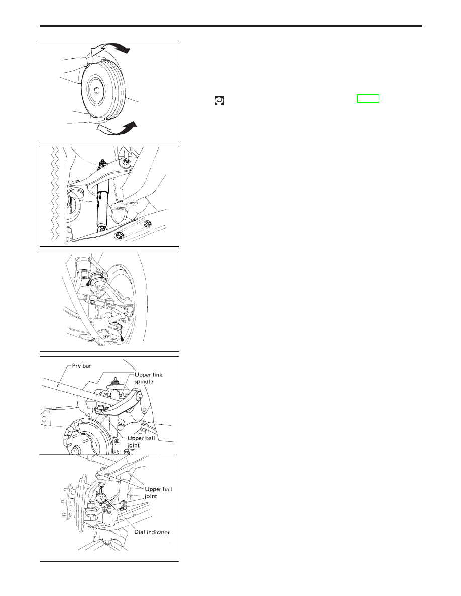
Check front axle and front suspension parts for looseness,
cracks, wear or other damage.

(1) Shake each front wheel.
(2) Make sure that cotter pin is inserted.
(3) Retighten all nuts and bolts to the specified torque.

: Refer to “FRONT SUSPENSION”, FA-29.

(4) Check front axle and front suspension parts for wear, cracks or

other damage.

I

Check shock absorber for oil leakage or other damage.

I

Check suspension ball joints for grease leakage and dust cov-
ers for cracks or other damage.

I

Check ball joint for vertical end play.

Upper ball joint:

1.6 mm (0.063 in) or less

(1) Jack up front of vehicle and set the stands.
(2) Clamp dial indicator onto transverse link and place indicator tip

on lower edge of brake caliper.

(3) Make sure front wheels are straight and brake pedal is

depressed.

(4) Place a pry bar between transverse link and inner rim of road

wheel.

(5) While pushing and releasing pry bar, observe maximum dial

indicator value.

(6) If ball joint movement is beyond specifications, remove and

recheck it.

SMA525A

SFA240

SMA241

SFA303A

CHECK AND ADJUSTMENT

FA-5

Lower ball joint:

0.5 mm (0.020 in) or less

(1) Jack up front of vehicle and set the stands.
(2) Remove road wheel.
(3) Clamp dial indicator onto upper link and place indicator tip on

knuckle near ball joint.

(4) Jack up lower link [Approx. 20 mm (0.79 in)].
(5) Place a pry bar between upper link and upper link spindle.
(6) While pushing and releasing pry bar observe maximum dial

indicator value.

(7) If ball joint movement is beyond specifications, remove and

recheck it.

Front Wheel Bearing

I

Check that wheel bearings operate smoothly.

I

Check axial end play.

Axial end play: 0 mm (0 in)

I

Adjust wheel bearing preload if there is any axial end play or
wheel bearing does not turn smoothly.

PRELOAD ADJUSTMENT

Adjust wheel bearing preload after wheel bearing has been
replaced or front axle has been reassembled.
Adjust wheel bearing preload as follows:
1. Before adjustment, thoroughly clean all parts to prevent dirt

entry.

2. Apply multi-purpose grease sparingly to the following parts:

I

Threaded portion of spindle

I

Contact surface between wheel bearing washer and outer
wheel bearing

I

Grease seal lip

I

Wheel hub (as shown at left)

SFA302A

SMA571A

YFA008

CHECK AND ADJUSTMENT

Front Axle and Front Suspension Parts
(Cont’d)

FA-6

3. Tighten wheel bearing lock nut with Tool.

: 78 - 98 N

m

(8 - 10 kg-m, 58 - 72 ft-lb)

4. Turn wheel hub several times in both directions.
5. Loosen wheel bearing lock nut so that torque becomes 0 N

m

(0 kg-m, 0 ft-lb).

6. Retighten wheel bearing lock nut with Tool.

: 0.5 - 1.5 N

m

(0.05 - 0.15 kg-m, 4 - 13 in-lb)

7. Turn wheel hub several times in both directions.
8. Retighten wheel bearing lock nut with Tool.

: 0.5 - 1.5 N

m

(0.05 - 0.15 kg-m, 4 - 13 in-lb)

9. Measure wheel bearing axial end play.

Axial end play:

0 mm (0 in)

10. Measure starting force “A” at wheel hub bolt when moving the

hub by 90° as shown.

11. Install lock washer by tightening the lock nut within 15 to 30

degrees.

12. Turn wheel hub several times in both directions to seat wheel

bearing correctly.

13. Measure starting force “B” at wheel hub bolt. Refer to proce-

dure 10.

14. Wheel bearing preload “C” can be calculated as shown below.

C = B − A

Wheel bearing preload “C”:

7.06 - 20.99 N
(0.72 - 2.14 kg, 1.59 - 4.72 lb)

15. Repeat above procedures until correct axial end play and wheel

bearing preload are obtained.

16. Install free-running hub and brake pads.

YFA009

SFA892

YFA004

SFA830

CHECK AND ADJUSTMENT

Front Wheel Bearing (Cont’d)

FA-7

Front Wheel Alignment

Before checking front wheel alignment, be sure to make a prelimi-
nary inspection.

PRELIMINARY INSPECTION

1. Check the tires for wear and proper inflation.

2. Check the wheel runout.

Wheel runout:

Refer to SDS, FA-39.

3. Check the front wheel bearings for looseness.
4. Check the front suspension for looseness.
5. Check the steering linkage for looseness.
6. Check that the front shock absorbers work properly by using

the standard bounce test.

7. Measure vehicle height (Unladen): H = A − B mm (in)

Refer to SDS, FA-39.

(1) Exercise the front suspension by bouncing the front of the

vehicle 4 or 5 times to ensure that vehicle is in a neutral height
attitude.

(2) Measure wheel alignment.

Refer to SDS, FA-39.

(3) Measure vehicle posture ... Dimension “H”.

Refer to SDS, FA-39.

If “H” dimension is not within the specified value, readjust
vehicle posture using anchor arm adjusting nut.
Refer to “INSTALLATION AND ADJUSTMENT”, “Torsion Bar
Spring”, FA-31. Adjust wheel alignment if necessary.

(4) If wheel alignment is not as specified, but dimension “H” is

correct, adjust wheel alignment.

CAMBER, CASTER AND KINGPIN INCLINATION

Before checking camber, caster or kingpin inclination, move
vehicle up and down on turning radius gauge to minimize
friction. Ensure that vehicle is in correct posture (unladen
vehicle).

I

Measure camber, caster and kingpin inclination of both
right and left wheels with a suitable alignment gauge and
adjust in accordance with the following procedures.

SFA893

NFA001

SFA894

CHECK AND ADJUSTMENT

FA-8


Content   ..  314  315  316  317   ..