Nissan Terrano r20e. Manual - part 183


  Index      Nissan     Nissan Terrano r20e - Service and Repair Manual


Search            


Content   ..  181  182  183  184   ..


Nissan Terrano r20e. Manual - part 183


ACCELERATOR POSITION SWITCH

The accelerator position switch detects OFF-accelerator switch sig-
nal and Full-accelerator switch signal and sends these signals to
the ECM. The ECM will then determine engine idle conditions.
These signals are also used for diagnosing the accelerator position
sensor.

INSPECTION START

CHECK OVERALL FUNCTION.
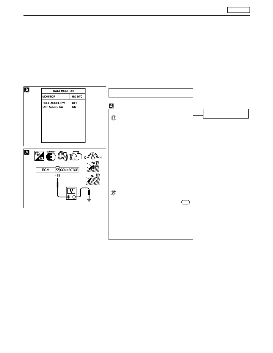
With CONSULT-II

1. Turn ignition switch to “ON” position.
2. Select “FULL ACCELL SW” and “OFF

ACCEL SW” in “DATA MONITOR” mode
with CONSULT-II.

3. Check “FULL ACCEL SW” and “OFF

ACCEL SW” signal under the following
conditions.
OFF ACCEL SW:

Accelerator pedal released
— ON
Accelerator pedal depressed
— OFF

FULL ACCEL SW:

Accelerator pedal fully depressed
— ON

Without CONSULT-II

1. Turn ignition switch to “ON” position.
2. Check voltage between ECM terminal

435

and body ground under the following condi-
tions:
Voltage:

Accelerator pedal released

Approximately 0V

Accelerator pedal fully depressed

Approximately 5V

NG

E

OK

INSPECTION END

q

A

MEC969D

MEC955D

H

H

DTC P0120 ACCEL POS SENSOR

TD27Ti

Diagnostic Procedure (Cont’d)

EC-369

q

A

CHECK INPUT SIGNAL CIRCUIT.
1. Turn ignition switch to “LOCK” position.
2. Disconnect accelerator work unit har-

ness connector and ECM harness con-
nector.

3. Check harness continuity between

accelerator work unit terminal

q

3

and

ECM terminal

435

. Refer to wiring

diagram.
Continuity should exist.
Check harness for short-circuit.

OK

E

NG

Check the following:

I

10A fuse in fuse box

I

75A fusible link in fusible
link box

I

Harness continuity
between ECM relay and
battery positive supply

I

Harness for open or
short-circuit between
ECM relay and accelera-
tor position switch.

If NG, repair harness or
connectors.

CHECK GROUND CIRCUIT.
1. Turn ignition switch to “LOCK” position.
2. Disconnect ECM harness connector.
3. Check harness continuity between

accelerator work unit connector termi-
nal

q

1

and ECM connector terminal

426

. Refer to wiring diagram.

Continuity should exist.
If OK; check harness for short-circuit.
If OK, re-connect harness connectors.

OK

E

NG

Repair harness or connec-
tors.

CHECK COMPONENT.
(Accelerator position switch.)
Refer to “COMPONENT INSPECTION” on
page EC-371.

OK

E

NG

Replace accelerator pedal.

Disconnect and reconnect harness con-
nectors in the circuits. Then retest.

Trouble is not fixed

Check ECM pin terminals for damage and
check the connection of ECM harness
connector. Reconnect ECM harness con-
nector and retest.

INSPECTION END

SEF628S

H

H

H

H

H

H

DTC P0120 ACCEL POS SENSOR

TD27Ti

Diagnostic Procedure (Cont’d)

EC-370

Component Inspection

ACCELERATOR POSITION SENSOR

1. Disconnect accelerator work unit harness connector.
2. Make sure that resistance between terminals

q

2

and

q

4

changes

when opening throttle valve manually.

Throttle valve conditions

Resistance [at 25°C (77°F)]

Completely closed

Approximately 1.2 k

Partially open

1.2 - 1.9 k

Completely open

Approximately 1.9 k

If NG, replace accelerator pedal assembly.

CAUTION

I

Do not disassemble accelerator pedal assembly.

ACCELERATOR POSITION SWITCH

1. Disconnect accelerator work unit harness connector.
2. Check continuity between terminals

q

1

and

q

3

.

Conditions

Continuity

Accelerator pedal released

No

Accelerator pedal depressed

Yes

If NG, replace accelerator pedal assembly.

CAUTION:

I

Do not disassemble accelerator pedal assembly.

MEC960D

MEC961D

DTC P0120 ACCEL POS SENSOR

TD27Ti

EC-371

Component Description

FUEL TEMPERATURE SENSOR (FTS)

The fuel temperature sensor is used to detect the fuel temperature
in the injection pump. The sensor modifies a voltage signal from the
ECM. The modified signal returns to the ECM as the fuel tempera-
ture input. The sensor uses a thermistor which is sensitive to the
change in temperature. The electrical resistance of the thermistor
decreases as temperature increases.
The sensor is built into the inside electrical circuit of the injection
pump.

On Board Diagnosis Logic

DTC

Malfunction is detected when ...

Check Items

(Possible Cause)

P0180
0402

I

An excessively high or low voltage from the sensor is
detected by ECM.

I

Harness or connectors
(The sensor circuit is open or short-circuited.)

I

Fuel temperature sensor

DTC Confirmation Procedure

WITH CONSULT-II

1) Turn ignition switch to “ON” position.
2) Select “DATA MONITOR” mode with CONSULT-II.
3) Wait at least 5 seconds.

WITHOUT CONSULT-II

1) Turn ignition switch to “ON” position and wait at least 5 sec-

onds.

2) Turn ignition switch to “LOCK” position, wait at least 5 seconds

and then turn to “ON” position.

3) Perform “Diagnostic Test Mode II” (Self-diagnostic results).

DTC P0180 FUEL TEMP SENSOR

TD27Ti

EC-372


Content   ..  181  182  183  184   ..