Nissan Terrano r20e. Manual - part 182


  Index      Nissan     Nissan Terrano r20e - Service and Repair Manual


Search            


Content   ..  180  181  182  183   ..


Nissan Terrano r20e. Manual - part 182


Component Description

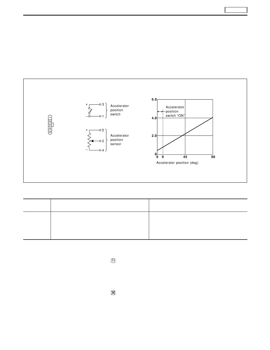
ACCELERATOR WORK UNIT

The accelerator position sensor is installed on the upper end of the
accelerator pedal assembly. The sensor detects the accelerator
position and sends a signal to the ECM. The ECM uses the signal
to determine the amount of fuel to be injected.
The accelerator position switch is installed inside the accelerator
position sensor. This switch is used for plausibility check of the
accelerator position sensor.

On Board Diagnosis Logic

DTC

Malfunction is detected when ...

Check Items

(Possible Cause)

P0120
0403

I

An excessively low or high voltage from the sensor is
detected by the ECM.

I

Harness or connectors
(The sensor or switch circuit is open or
short-circuited.)

I

Accelerator position sensor

I

Accelerator position switch

DTC Confirmation Procedure A (For General
Plausibility)

WITH CONSULT-II

1) Turn ignition switch to “ON” position.
2) Select “DATA MONITOR” mode with CONSULT-II.
3) Depress accelerator pedal fully and keep it for at least 1 sec-

ond. Then release it and wait at least 5 seconds.

WITHOUT CONSULT-II

1) Turn ignition switch to “ON” position.
2) Depress accelerator pedal fully and keep it for at least 1 sec-

ond. Then release it and wait at least 5 seconds.

3) Turn ignition switch to “LOCK” position, wait at least 5 seconds

and then turn to “ON” position.

4) Perform “Diagnostic Test Mode II (Self-diagnostic results)” with

ECM.

MEC959D

DTC P0120 ACCEL POS SENSOR

TD27Ti

EC-365

DTC Confirmation Procedure B (For
Accelerator Sticking)

If DTC P0571 is displayed same time, cure it at first.

WITH CONSULT-II

1) Turn ignition switch to “ON” position.
2) Select “DATA MONITOR” mode with CONSULT-II.
3) Start engine and rev it up to above 1,300 rpm.
4) Depress brake pedal immediately after releasing accelerator

pedal and keep it at least 5 seconds.

WITHOUT CONSULT-II

1) Start engine and rev it up to above 1,300 rpm.
2) Depress brake pedal immediately after releasing accelerator

pedal and keep it at least 5 seconds.

3) Turn ignition switch to “LOCK” position, wait at least 5 seconds

and then turn to “ON” position.

4) Perform “Diagnostic Test Mode II (Self-diagnostic results)” with

ECM.

DTC P0120 ACCEL POS SENSOR

TD27Ti

EC-366

Wiring Diagram

YEC145A

DTC P0120 ACCEL POS SENSOR

TD27Ti

EC-367

Diagnostic Procedure

ACCELERATOR POSITION SENSOR

INSPECTION START

CHECK POWER SUPPLY.
1. Turn ignition switch to “LOCK” position.
2. Disconnect accelerator work unit har-

ness connector.

3. Turn ignition switch to “ON” position.
4. Check voltage between accelerator

work unit connector terminal

q

5

and

engine ground with CONSULT-II or
tester.
Voltage: Approximately 5V

OK

E

NG

Check the following:

I

Harness for open or
short-circuit between
ECM and accelerator
work unit.

If NG, repair harness or
connectors.

CHECK INPUT SIGNAL CIRCUIT.
1. Turn ignition switch to “LOCK” position.
2. Loosen and retighten engine ground

screws.

3. Check harness continuity between

accelerator work unit connector termi-
nal

q

2

and ECM connector terminal

434

. Refer to wiring diagram.

Continuity should exist.
If OK, check harness for short-circuit.

OK

E

NG

Check the following:

I

Harness for open-circuit
between ECM and
accelerator work unit

If NG, repair harness or
connectors.

CHECK GROUND CIRCUIT.
1. Disconnect ECM harness connector.
2. Check harness continuity between

ECM terminal

425

and accelerator

position sensor connector terminal

q

4

.

Refer to wiring diagram.
Continuity should exist.
If OK, check harness for short-circuit.

OK

E

NG

Repair harness or connec-
tors.

CHECK COMPONENT
(Accelerator position sensor).
Refer to “COMPONENT INSPECTION” on
page EC-371.

OK

E

NG

Replace accelerator pedal
assembly.

Disconnect and reconnect harness con-
nectors in the circuit. Then retest.

Trouble is not fixed.

Check ECM pin terminals for damage and
check the connection of ECM harness
connector. Reconnect ECM harness con-
nector and retest.

INSPECTION END

NEF700

NEF591

YEC246A

H

H

H

H

H

H

H

DTC P0120 ACCEL POS SENSOR

TD27Ti

EC-368


Content   ..  180  181  182  183   ..