Nissan Terrano r20e. Manual - part 179


  Index      Nissan     Nissan Terrano r20e - Service and Repair Manual


Search            


Content   ..  177  178  179  180   ..


Nissan Terrano r20e. Manual - part 179


Diagnostic Procedure

INSPECTION START

Start engine.
Is engine running?

Yes

E

No

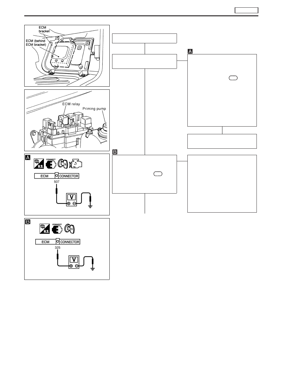
CHECK POWER SUPPLY-I.
1. Turn ignition switch to “ON” posi-

tion.

2. Check voltage between ECM

connector terminal

507

and

engine ground with
CONSULT-II or voltage tester.
Voltage: Battery voltage

If NG, check the following:

I

10A fuse

I

Harness for open or short-circuit
between ECM and ignition switch

If NG, replace 10A fuse or repair
harness or connectors.

OK

Go to

q

B

“CHECK GROUND CIR-

CUIT”.

CHECK POWER SUPPLY-II.
1. Stop engine.
2. Check voltage between ECM

connector terminal

325

and

engine ground with CON-
SULT-II or voltage tester.
Voltage: Battery voltage

OK

E

NG

Check the following:

I

ECM relay

I

20A fuse

I

Harness for open or short-circuit
between ECM and battery

I

Harness connectors M787, F66
(LHD models)

I

Battery connection and charge

If NG, replace fuse or charge bat-
tery or repair harness or connec-
tors.

q

A

NEF642

YEC283A

MEC946D

MEC943D

H

H

H

H

TROUBLE DIAGNOSIS FOR POWER SUPPLY

TD27Ti

EC-353

q

A

CHECK POWER SUPPLY-III.
1. Turn ignition switch to “ON” position

and then to “LOCK” position.

2. Check voltage between ECM connector

terminals

107

,

108

,

109

and engine

ground with CONSULT-II or tester.
Voltage:

After turning ignition switch to
“LOCK” position, battery voltage
will exist for a few seconds, then
drop to approximately 0V.

NG

E

OK

Go to

q

B

“CHECK

GROUND CIRCUIT”.

Case-1: Battery voltage does

not exist.

Case-2: Battery voltage exists

for more than a few
seconds.

Case-1

Case-2

E

Go to

“CHECK ECM

RELAY”.

CHECK HARNESS CONTINUITY
BETWEEN ECM RELAY AND ECM.
1. Disconnect ECM harness connector.
2. Disconnect ECM relay harness connec-

tor.

3. Check harness continuity between

ECM connector terminals

325

and

ECM relay connector terminal

q

2

, and

ECM connector terminals

107

,

108

,

109

and ECM relay connector termi-

nal

q

5

. Refer to wiring diagram.

Continuity should exist.
If OK, check harness for short-circuit.

OK

E

NG

Check the following:

I

Harness connectors

M787

,

F66

(LHD mod-

els)

I

Harness for open or
short-circuit between
ECM relay connector
and ECM connector.

If NG, repair harness or
connectors.

CHECK VOLTAGE BETWEEN ECCS
RELAY AND ENGINE GROUND.
Check voltage between ECM relay con-
nector terminals

q

1

,

q

3

and engine ground

with CONSULT-II or tester.
Voltage: Battery voltage

OK

E

NG

Check the following:

I

20A fuse

I

Fuse box and battery
connections

I

Harness for open or
short-circuit between
ECM relay and battery

If NG, replace fuse or
repair harness or connec-
tors.

CHECK ECM RELAY.
1. Remove ECM relay.
2. Apply 12V direct current between relay

terminals

q

1

and

q

2

.

3. Check continuity between relay termi-

nals

q

3

and

q

5

.

12V (

q

1

-

q

2

) applied:

Continuity exists.

No voltage applied:

No continuity

OK

E

NG

Replace ECM relay.

q

B

MEC944D

MEC945D

NEF350

H

H

H

H

H

TROUBLE DIAGNOSIS FOR POWER SUPPLY

TD27Ti

Diagnostic Procedure (Cont’d)

EC-354

q

B

CHECK GROUND CIRCUIT.
1. Turn ignition switch to “LOCK” position.
2. Disconnect ECM harness connector.
3. Check harness continuity between

ECM connector terminals

104

,

105

,

106

and engine ground. Refer to wir-

ing diagram.
Continuity should exist.
If OK, check harness for short-circuit.

OK

E

NG

Check the following:

I

Engine ground connec-
tions

I

Harness for open or
short-circuit between
ECM and engine ground

If NG, repair harness or
connectors.

Check ECM pin terminals for damage and
check the connection of ECM harness
connector.

INSPECTION END

H

H

H

TROUBLE DIAGNOSIS FOR POWER SUPPLY

TD27Ti

Diagnostic Procedure (Cont’d)

EC-355

Component Description

MASS AIR FLOW SENSOR (MAFS)

The mass air flow sensor measures the intake air flow rate by
monitoring a part of the entire flow. Measurements are made by the
ECM which receives electrical signals from the mass air flow sen-
sor which is proportional to the amount of heat emitted from the hot
wire placed in the stream of the intake air.
When intake air flows into the intake manifold through a route
around the hot wire, the heat generated by the hot wire is carried
away by the air flow. The amount of heat detected depends on the
volume of air flow. The temperature of the hot wire is automatically
controlled to maintain it within a finite range regardless of the air
flow rate by regulating the current supplied to the hot wire.
The ECM monitors the air flow by means of the corresponding
electric change.

On Board Diagnosis Logic

DTC

Malfunction is detected when . . .

Check Items

(Possible Cause)

P0100
0102

I

An excessively high or low voltage from the sensor is
entered to ECM.

I

Harness or connectors
(The sensor circuit is open or short-circuited.)

I

Mass air flow sensor

DTC Confirmation Procedure

WITH CONSULT-II

1) Turn ignition switch to “ON” position.
2) Select “DATA MONITOR” mode with CONSULT-II.
3) Start engine and wait for at least 15 seconds.

WITHOUT CONSULT-II

1) Start engine and wait for at least 15 seconds.
2) Turn ignition switch off, wait for at least 5 seconds and then turn

on.

3) Perform “Diagnostic Test Mode II” (Self-diagnostic results).

SEF781K

SEF817Y

DTC P0100 MASS AIR FLOW SEN

TD27Ti

EC-356


Content   ..  177  178  179  180   ..