Nissan Terrano r20e. Manual - part 177


  Index      Nissan     Nissan Terrano r20e - Service and Repair Manual


Search            


Content   ..  175  176  177  178   ..


Nissan Terrano r20e. Manual - part 177


Major Sensor Reference Graph in Data Monitor
Mode

The following are the major sensor reference graphs in “DATA MONITOR” mode.
(Select “HI SPEED” in “DATA MONITOR” with CONSULT-II.)

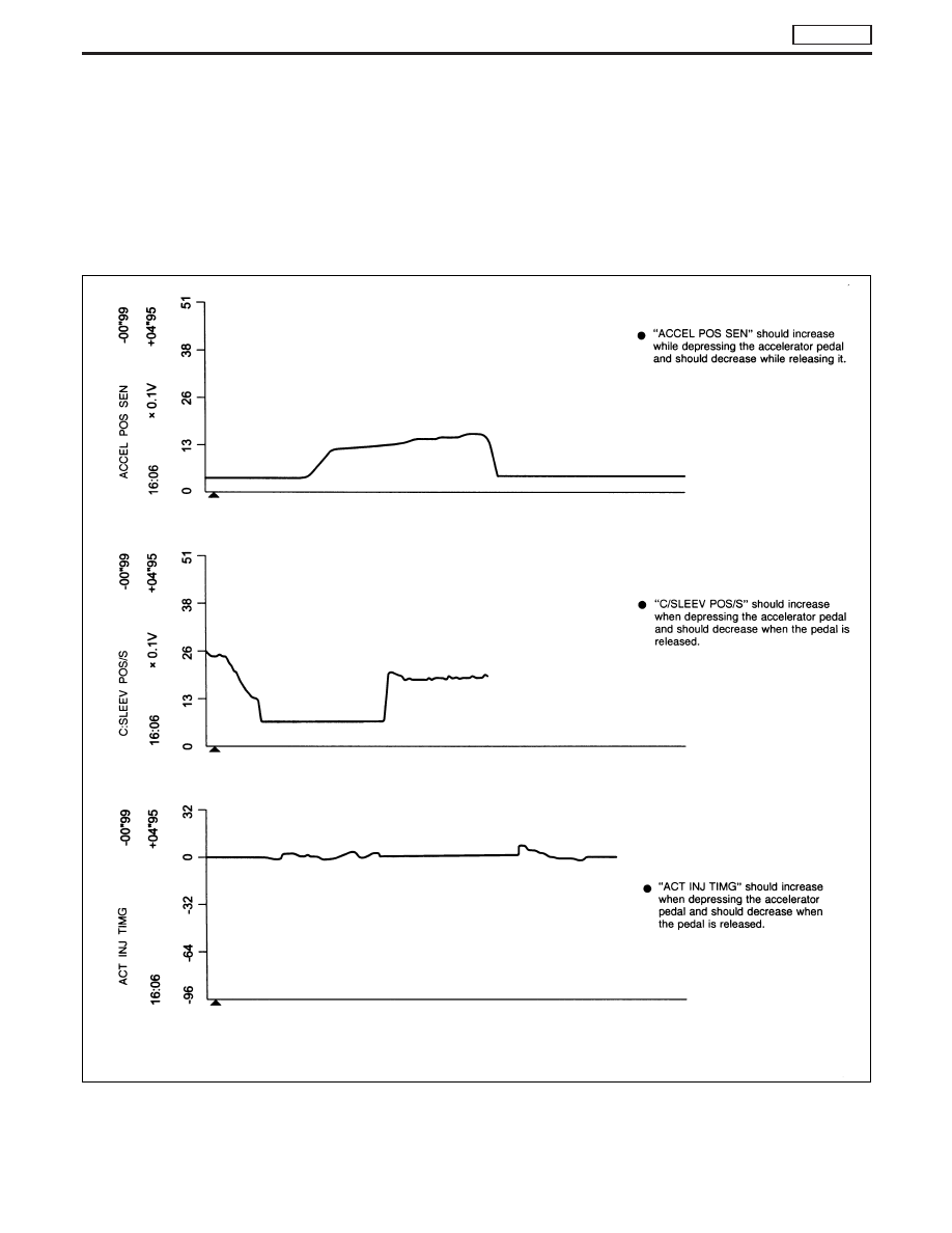
ACCEL POS SEN, C/SLEEV POS/S, ACT INJ TIMG

Below is the data for “ACCEL POS SEN”, “C/SLEEV POS/S” and “ACT INJ TIMG” when revving engine quickly
up to 3,000 rpm under no load after warming up engine sufficiently.
Each value is for reference, the exact value may vary.

NEF766

TROUBLE DIAGNOSES

TD27Ti

EC-345

ECM Terminals and Reference Value

PREPARATION

Perform all voltage measurements with all the connectors con-
nected. Measure ECM terminal voltage at the nearest connector to
the sensors or actuators to be measured as accessing ECM termi-
nals from outside is impossible.

I

Use extreme care not to touch 2 pins at the same time.

I

Data is for comparison and may not be exact.

I

Use care not to enlarge the opening to keep the seal in good
condition.

Be sure ECM unit is properly grounded before checking.

ECM HARNESS CONNECTOR TERMINAL LAYOUT

SGI841

MEC032E

TROUBLE DIAGNOSES

TD27Ti

EC-346

ECM INSPECTION TABLE

Remarks: Specification data are reference values and are measured between each terminal and ground.

CAUTION:

Do not use ECM ground terminals when measuring input/output voltage. Doing so may result in dam-
age to the ECM’s transistor. Use a ground other than ECM terminals, such as the ground.

TERMI-

NAL

NO.

WIRE

COLOR

ITEM

CONDITION

DATA (DC Voltage and

Pulse Signal)

101
102
103

G/R
G/R
G/R

Fuel cut solenoid valve

[Ignition switch “OFF”]

Approximately 0V

[Ignition switch “ON”]

BATTERY VOLTAGE
(11 - 14V)

104
105
106

B
B
B

ECM ground

[Engine is running]

I

Idle speed

Approximately 0V

107
108
109

Y
Y
Y

Power supply for ECM

[Ignition switch “ON”]

BATTERY VOLTAGE
(11 - 14V)

202

Y/R

Injection timing control
valve

[Engine is running]

I

Warm-up condition

I

Idle speed

Approximately 10 - 12V

NEF480

[Engine is running]

I

Warm-up condition

I

Engine speed is 2,000 rpm

Approximately 9 - 14 V

NEF481

204

G/PU

Air conditioner relay

[Engine is running]

I

Air conditioner switch is “OFF”

BATTERY VOLTAGE
(11 - 14V)

[Engine is running]

I

Both air conditioner switch and blower fan switch
are “ON”
(Compressor is operating)

Approximately 0.1V

205

Y/PU

Oil pressure switch

[Ignition switch “ON”]

Approximately 0V

[Engine is running]

I

Idle speed

Voltages

208

R/Y

EGRC-solenoid valve A

[Engine is running]

I

Warm-up condition

I

Idle speed

Approximately 0.7V

[Engine is running]

I

Warm-up condition

I

Engine speed is 2,800 rpm

BATTERY VOLTAGE
(11 - 14V)

TROUBLE DIAGNOSES

TD27Ti

ECM Terminals and Reference Value (Cont’d)

EC-347

TERMI-

NAL

NO.

WIRE

COLOR

ITEM

CONDITION

DATA (DC Voltage and

Pulse Signal)

210

Y/B

EGRC-solenoid valve B

[Engine is running]

I

Warm-up condition

I

Idle speed

Approximately 0.4V

[Engine is running]

I

Warm-up condition

I

Engine speed is 2,500 rpm

BATTERY VOLTAGE
(11 - 14V)

213

G/Y

Throttle control solenoid
valve

[Engine is running]

I

Warm-up condition

I

Low load

Approximately 0V

Except above condition

Battery voltage (12 - 14V)

214

LG

Glow relay

Refer to “Glow Control System”, EC-389.

215

L

Malfunction indicator (MI)

[Ignition switch “ON”]

Approximately 1.0V

[Engine is running]

I

Idle speed

BATTERY VOLTAGE
(11 - 14V)

218

G/R

Sensors’ ground

[Engine is running]

I

Warm-up condition

I

Idle speed

Approximately 0V

219

LG/R

Cooling fan relay

[Engine is running]

I

Cooling fan is not operating

BATTERY VOLTAGE
(11 - 14V)

[Engine is running]

I

Cooling fan is operating

Approximately 0.1V

221

G/W

Glow lamp

[Ignition switch “ON”]

I

Glow lamp is “ON”

Approximately 1V

[Ignition switch “ON”]

I

Glow lamp is “OFF”

BATTERY VOLTAGE
(11 - 14V)

223

R/L

Mass air flow sensor
power supply

[Ignition switch “ON”]

Approximately 5V

224

L/W

Mass air flow sensor

[Engine is running]

I

Warm-up condition

I

Idle speed

1.5 - 2.0V

320

W

Control sleeve position
sensor

[Engine is running]

I

Idle speed

Approximately 2.6V

NEF477

321

R

Control sleeve position
sensor power supply

[Engine is running]

I

Idle speed

Approximately 2.6V

NEF476

TROUBLE DIAGNOSES

TD27Ti

ECM Terminals and Reference Value (Cont’d)

EC-348


Content   ..  175  176  177  178   ..