Nissan Terrano r20e. Manual - part 174


  Index      Nissan     Nissan Terrano r20e - Service and Repair Manual


Search            


Content   ..  172  173  174  175   ..


Nissan Terrano r20e. Manual - part 174


SEF720X

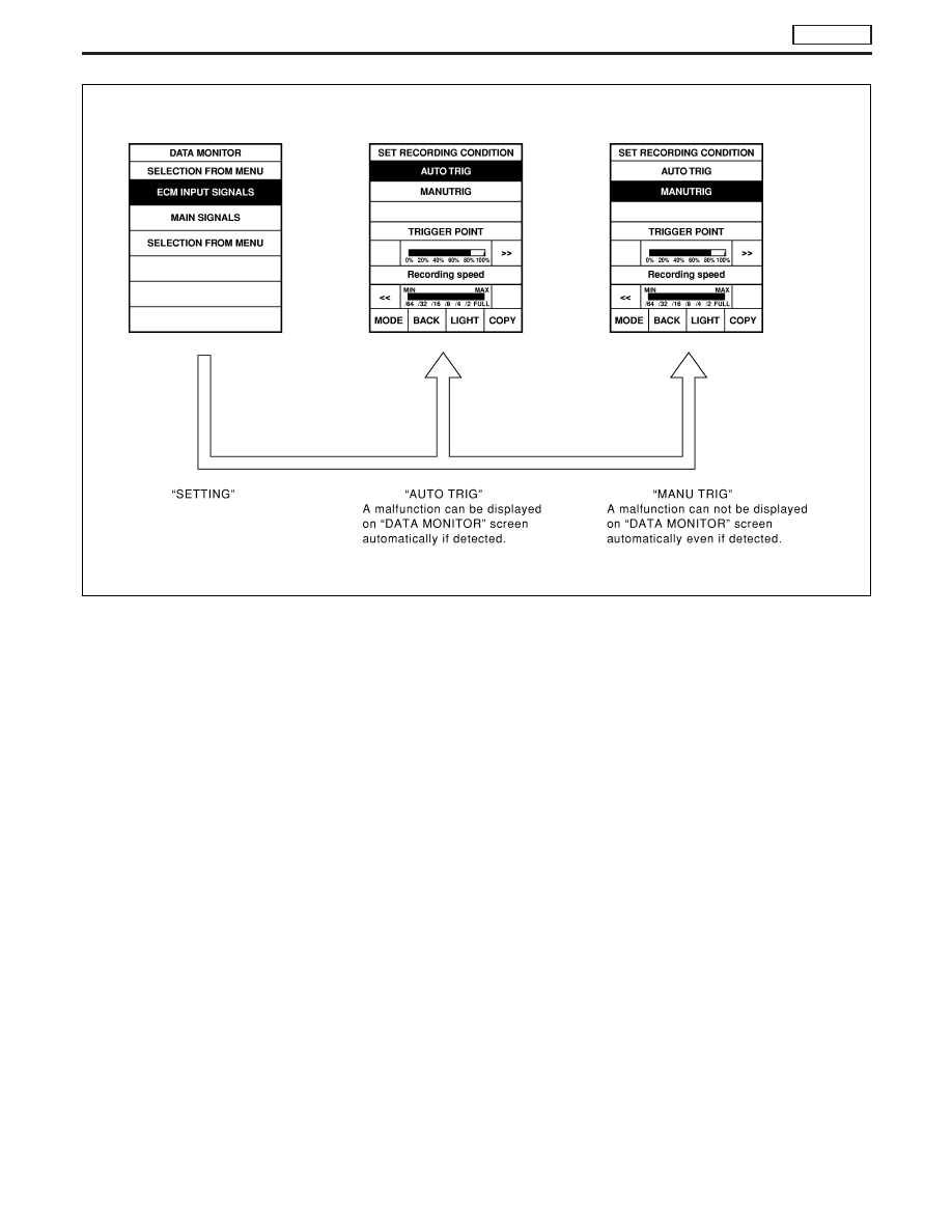
ON BOARD DIAGNOSTIC SYSTEM DESCRIPTION

TD27Ti

CONSULT-II (Cont’d)

EC-333

Introduction

The engine has an ECM to control major systems such as fuel
injection control, fuel injection timing control, glow control system,
etc. The ECM accepts input signals from sensors and instantly
drives electronic fuel injection pump. It is essential that both input
and output signals are correct and stable. It is also important that
there are no problems such as vacuum leaks, with the engine.
It is much more difficult to diagnose a problem that occurs intermit-
tently rather than continuously. Most intermittent problems are
caused by poor electric connections or faulty wiring. In this case,
careful checking of suspected circuits may help prevent the unnec-
essary replacement of good parts.
A visual check may not be sufficient to determine the cause of the
problems. An active road test with CONSULT-II or a circuit tester
connected should be performed. Follow the “Work Flow” on the
next page.
Before undertaking actual checks, take a few minutes to talk with
a customer who approaches with a driveability complaint. The cus-
tomer can supply important information about such problems,
especially intermittent ones. Find out what symptoms are present
and under what conditions they occur. A “Diagnostic Worksheet”
like the example on the next page should be used.
Start your diagnosis by looking for “conventional” problems first.
This will help troubleshoot driveability problems on a vehicle with
an electronically controlled engine.

SEF858S

SEF233G

SEF234G

TROUBLE DIAGNOSES

TD27Ti

EC-334

Diagnostic Worksheet

There are many operating conditions that lead to the malfunction
of engine components. A good understanding of such conditions
can make troubleshooting easier and more accurate.
In general, each customer feels differently about a problem. It is
important to fully understand the symptoms or conditions for a
customer complaint.
Utilize a diagnostic worksheet like the one shown below in order to
organize all the information for troubleshooting.

WORKSHEET SAMPLE

Customer name

MR/MS

Model & Year

VIN

Engine #

Trans.

Mileage

Incident Date

Manuf. Date

In Service Date

Symptoms

l

Startability

l

Impossible to start

l

No combustion

l

Partial combustion

l

Partial combustion when warming-up engine

l

Partial combustion when cooling down engine

l

Possible but hard to start

l

Others [

]

l

Idling

l

No fast idle

l

Unstable

l

High idle

l

Low idle

l

Others [

]

l

Driveability

l

Stumble

l

Surge

l

Knock

l

Lack of power

l

Others [

]

l

Engine stall

l

At the time of start

l

While idling

l

While accelerating

l

While decelerating

l

Just after stopping

l

While loading

Incident occurrence

l

Just after delivery

l

Recently

l

In the morning

l

At night

l

In the daytime

Frequency

l

All the time

l

Under certain conditions

l

Sometimes

Weather conditions

l

Not affected

Weather

l

Fine

l

Raining

l

Snowing

l

Others [

]

Temperature

l

Hot

l

Warm

l

Cool

l

Cold

l

Humid

°F

Engine conditions

l

Cold

l

During warm-up

l

After warm-up

Engine speed

0

2,000

4,000

6,000

8,000 rpm

Road conditions

l

In town

l

In suburbs

l

Highway

l

Off road (up/down)

Driving conditions

l

Not affected

l

At starting

l

While idling

l

At racing

l

While accelerating

l

While cruising

l

While decelerating

l

While turning (RH/LH)

Vehicle speed

0

10

20

30

40

50

60

70

80

90

100 mph

Malfunction indicator lamp

l

Turned on

l

Not turned on

SEF907L

TROUBLE DIAGNOSES

TD27Ti

EC-335

Work Flow

CHECK IN

Listen to customer complaints. (Get symptoms.)

................................................. STEP I

Check, print out or write down, and erase Diagnostic Trouble Code (DTC).

........................................... STEP II

Symptoms
collected.

No symptoms, except MI
lights up, or Malfunction
Code exists at STEP II.

Verify the symptom by driving in the condition the cus-
tomer described.

H

*1

............................................................................................. STEP III

Normal Code
(at STEP II)

Malfunction Code
(at STEP II)

Verify the DTC by performing the “DTC CONFIRMATION PROCEDURE”.

*1

........................................... STEP IV

E

Choose the appropriate action.

Malfunction Code (at STEP II or IV)

Normal Code (at both STEP II and IV)

...........................................

*2

STEP V

BASIC INSPECTION

SYMPTOM BASIS (at STEP I or III)

................................................................

E

Perform inspections
according to Symptom
Matrix Chart.

TROUBLE DIAGNOSIS FOR DTC (See TROUBLE DIAGNOSIS — INDEX,
EC-293).

STEP VI

REPAIR/REPLACE

NG

FINAL CHECK
Confirm that the incident is completely fixed by performing BASIC INSPECTION and
DTC CONFIRMATION PROCEDURE (or OVERALL FUNCTION CHECK). Then,
erase the unnecessary (already fixed) DTCs in ECM.

OK

........................................... STEP VII

CHECK OUT

*1: If the incident cannot be duplicated, refer to GI section.
*2: If the on board diagnostic system cannot be performed, check main power supply and ground circuit. Refer to

“TROUBLE DIAGNOSIS FOR POWER SUPPLY”, EC-352.

H

H

H

H

H

H

H

H

H

H

H

TROUBLE DIAGNOSES

TD27Ti

EC-336


Content   ..  172  173  174  175   ..