Nissan Terrano r20e. Manual - part 45


  Index      Nissan     Nissan Terrano r20e - Service and Repair Manual


Search            


Content   ..  43  44  45  46   ..


Nissan Terrano r20e. Manual - part 45


Assembly (1)

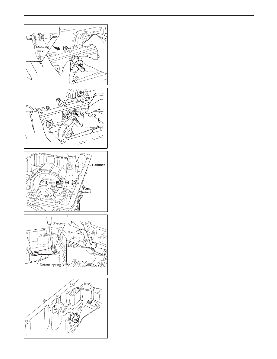
1. Install manual shaft components.
a. Install oil seal onto manual shaft.

I

Apply ATF to oil seal.

I

Wrap threads of manual shaft with masking tape.

b. Insert manual shaft and oil seal as a unit into transmission

case.

c. Remove masking tape.

d. Push oil seal evenly and install it onto transmission case.

e. Align groove in shaft with drive pin hole, then drive pin into

position as shown in figure at left.

f.

Install detent spring and spacer.

g. While pushing detent spring down, install manual plate onto

manual shaft.

h. Install lock nuts onto manual shaft.

SAT931A

SAT932A

SAT933A

SAT901E

SAT936A

ASSEMBLY

AT-177

2. Install accumulator piston.
a. Install O-rings onto accumulator piston.

I

Apply ATF to O-rings.

Accumulator piston O-rings

Unit: mm (in)

Accumulator

q

A

q

B

q

C

q

D

Small diameter end

29 (1.14)

32 (1.26)

45 (1.77)

29 (1.14)

Large diameter end

45 (1.77)

50 (1.97)

50 (1.97)

45 (1.77)

b. Install return spring for accumulator A onto transmission case.

Free length of return spring:

Refer to SDS, AT-197.

c. Install accumulator pistons

q

A

,

q

B

,

q

C

and

q

D

.

I

Apply ATF to transmission case.

3. Install band servo piston.
a. Install return springs onto servo piston.

b. Install band servo piston onto transmission case.

I

Apply ATF to O-ring of band servo piston and transmission
case.

c. Install gasket for band servo onto transmission case.

SAT523GA

SAT938A

SAT939AA

SAT941A

SAT942A

ASSEMBLY

Assembly (1) (Cont’d)

AT-178

d. Install band servo retainer onto transmission case.

4. Install rear side clutch and gear components.
a. Place transmission case in vertical position.

b. Slightly lift forward clutch drum assembly. Then slowly rotate it

clockwise until its hub passes fully over clutch inner race inside
transmission case.

c. Check to be sure that rotation direction of forward clutch

assembly is correct.

d. Install thrust washer onto front of overrun clutch hub.

I

Apply petroleum jelly to the thrust washer.

I

Insert pawls of thrust washer securely into holes in over-
run clutch hub.

SAT940A

NAT303

SAT944A

SAT945A

SAT946A

ASSEMBLY

Assembly (1) (Cont’d)

AT-179

e. Install overrun clutch hub onto rear internal gear assembly.

f.

Install needle bearing onto rear of overrun clutch hub.

I

Apply petroleum jelly to needle bearing.

g. Check that overrun clutch hub rotates as shown while holding

forward clutch hub.

h. Place transmission case into horizontal position.

i.

Install rear internal gear, forward clutch hub and overrun clutch
hub as a unit onto transmission case.

SAT947A

SAT948A

SAT949A

NAT304

SAT951A

ASSEMBLY

Assembly (1) (Cont’d)

AT-180


Content   ..  43  44  45  46   ..