Nissan Titan. Manual - part 304
EM-20
< PERIODIC MAINTENANCE >
CAMSHAFT VALVE CLEARANCE
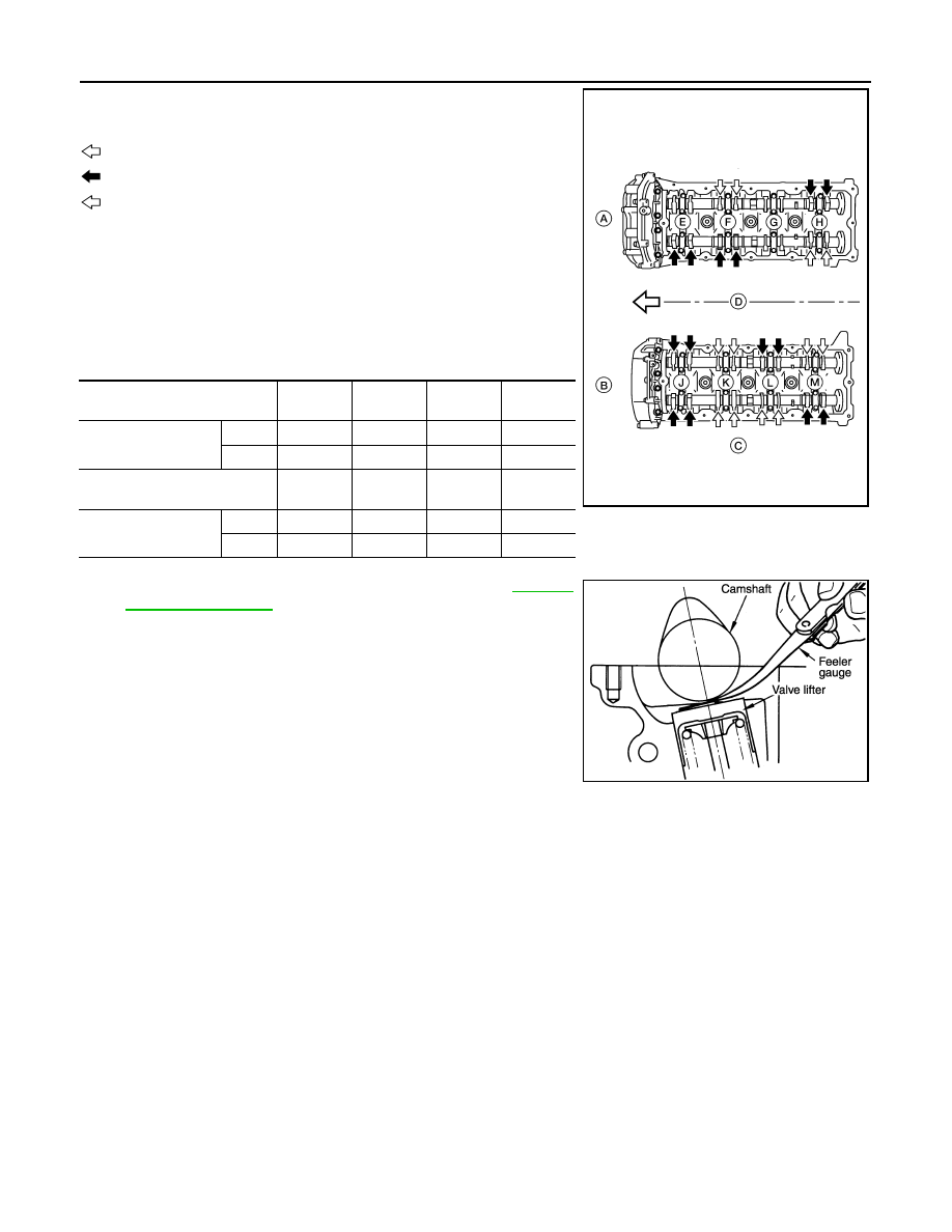
6. Measure valve clearances at the locations marked “
×” as shown
in the table below (locations indicated with black arrow).
NOTE:
Firing order 1-8-7-3-6-5-4-2
• No. 1 cylinder compression TDC
• Measure valve clearance using suitable tool. Refer to
CAUTION:
If the inspection was carried out with a cold engine, make
sure the values with a fully warmed up engine are still
within specifications.
7. Turn the crankshaft pulley clockwise 270
° from the position of No. 1 cylinder compression TDC to obtain
No. 3 cylinder compression TDC.
: Engine front
: Measurable at No.1 cylinder compression top dead center (black)
: Measurable at No. 3 cylinder compression top dead center (white)
(A)
: (RH)
(B)
: (LH)
(C)
: Exhaust
(D)
: Intake
Measuring position (RH bank)
No. 2 cyl
(E)
No. 4 cyl
(F)
No. 6 cyl
(G)
No. 8 cyl
(H)
No. 1 cylinder at TDC
EXH
×
INT
×
×
Measuring position (LH bank)
No. 1 cyl
(J)
No. 3 cyl
(K)
No. 5 cyl
(L)
No. 7 cyl
(M)
No. 1 cylinder at TDC
INT
×
×
EXH
×
×
WBIA0713E
KBIA0185E