Nissan Titan. Manual - part 302


  Index      Nissan     Nissan Titan (2014 year) - Service and Repair Manual


Search            


Content   ..  300  301  302  303   ..


Nissan Titan. Manual - part 302


EM-12

< SYSTEM DESCRIPTION >

NOISE, VIBRATION, AND HARSHNESS (NVH) TROUBLESHOOTING

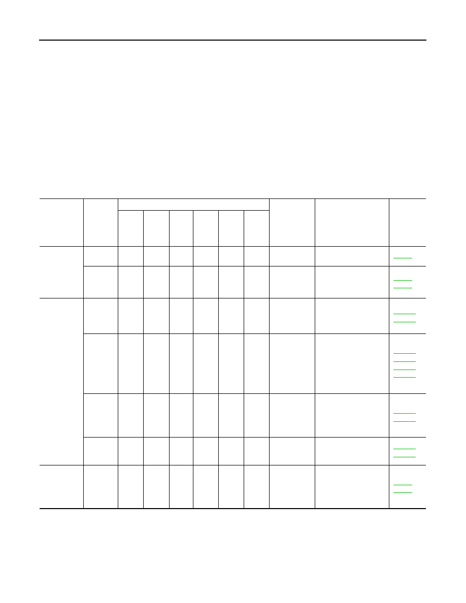
Use the Chart Below to Help You Find the Cause of the Symptom

INFOID:0000000009886398

1. Locate the area where noise occurs.
2. Confirm the type of noise.
3. Specify the operating condition of engine.
4. Check specified noise source.
If necessary, repair or replace these parts.

1.

Timing chain

2.

Intake valve

3.

Exhaust valve

4.

Drive belt

5.

Water pump

A.

VTC noise

B.

Tappet noise

C.

Camshaft bearing noise

D.

Valve mechanism

E.

Rotation mechanism

F.

Piston pin noise

G.

Piston slap noise

H.

Main bearing noise

I.

Connecting rod bearing noise

J.

Drive belt noise (slipping)

K.

Drive belt noise (stick/slipping)

L.

Water pump noise

M.

Timing chain and chain tensioner noise

Location of 

noise

Type of 

noise

Operating condition of engine

Source of 

noise

Check item

Refer-

ence page

Be-

fore 

warm-

up

After 

warm-

up

When 

start-

ing

When 

idling

When 

racing

While 

driv-

ing

Top of en-
gine
Rocker cov-
er
Cylinder 
head

Ticking or 
clicking

C

A

A

B

Tappet noise

Valve clearance

EM-19

Rattle

C

A

A

B

C

Camshaft 
bearing noise

Camshaft journal clear-
ance
Camshaft runout

EM-62
EM-62

Crankshaft 
pulley
Cylinder 
block (Side 
of engine)
Oil pan

Slap or 
knock

A

B

B

Piston pin 
noise

Piston and piston pin 
clearance
Connecting rod bushing 
clearance

EM-101
EM-101

Slap or 
rap

A

B

B

A

Piston slap 
noise

Piston-to-bore clear-
ance
Piston ring side clear-
ance
Piston ring end gap
Connecting rod bend 
and torsion

EM-101
EM-101
EM-101
EM-101

Knock

A

B

C

B

B

B

Connecting 
rod bearing 
noise

Connecting rod bushing 
oil clearance (Small 
end)
Connecting rod bearing 
clearance (Big end)

EM-101
EM-101

Knock

A

B

A

B

C

Main bearing 
noise

Main bearing oil clear-
ance
Crankshaft runout

EM-101
EM-101

Front of en-
gine
Chain case 
cover
Front cover

Tapping 
or ticking

A

A

B

B

B

Timing chain 
and chain 
tensioner 
noise

Timing chain cracks 
and wear
Timing chain tensioner 
operation

EM-50
EM-57

NOISE, VIBRATION, AND HARSHNESS (NVH) TROUBLESHOOTING

EM-13

< SYSTEM DESCRIPTION >

C

D

E

F

G

H

I

J

K

L

M

A

EM

N

P

O

A: Closely related B: Related C: Sometimes related —: Not related

Front of en-
gine

Squeak-
ing or 
fizzing

A

B

B

C

Drive belts 
(Sticking or 
slipping)

Drive belts deflection

EM-14

Creaking

A

B

A

B

A

B

Drive belts 
(Slipping)

Idler pulley bearing op-
eration

Squall
Creaking

A

B

B

A

B

Water pump 
noise

Water pump operation

CO-20

Rattle

A

VTC

VTC lock pin clearance

EM-71

Location of 

noise

Type of 

noise

Operating condition of engine

Source of 

noise

Check item

Refer-

ence page

Be-

fore 

warm-

up

After 

warm-

up

When 

start-

ing

When 

idling

When 

racing

While 

driv-

ing

EM-14

< PERIODIC MAINTENANCE >

DRIVE BELTS

PERIODIC MAINTENANCE

DRIVE BELTS

Checking Drive Belts

INFOID:0000000009886399

WARNING:

Be sure to perform when the engine is stopped.
1. Remove air duct and resonator assembly when inspecting drive belt.
2. Make sure that indicator (single line notch) of each drive belt auto-tensioner is within the allowable work-

ing range (between three line notches).

NOTE:

• Check the drive belt auto-tensioner indication when the engine is cold.

• The indicator notch is located on the moving side of the drive belt auto-tensioner. 

3. Visually check entire drive belt for wear, damage or cracks.
4. If the indicator is out of allowable working range or drive belt is damaged, replace the drive belt. Refer to

EM-14

.

DRIVE BELT TENSION

There is no manual drive belt tension adjustment. The drive belt tension is automatically adjusted by the drive

belt auto-tensioner.

Removal and Installation

INFOID:0000000009886400

REMOVAL

1. Remove the air duct and resonator assembly. Refer to 

EM-26, "Removal and Installation"

.

1.

Drive belt

2.

Power steering pump pulley

3.

Generator pulley

4.

Crankshaft pulley

5.

A/C compressor

6.

Idler pulley

7.

Cooling fan pulley

8.

Water pump pulley

9.

Drive belt auto-tensioner

A.

Allowable working range

LBIA0391E

DRIVE BELTS

EM-15

< PERIODIC MAINTENANCE >

C

D

E

F

G

H

I

J

K

L

M

A

EM

N

P

O

2. Install Tool on drive belt auto-tensioner pulley bolt, move in the

direction of arrow (loosening direction of tensioner) as shown.

WARNING:

Avoid placing hand in a location where pinching may occur

if the holding tool accidentally comes off.

3. Remove the drive belt. 

INSTALLATION

Installation is in the reverse order of removal.

CAUTION:

Make sure belt is securely installed around all pulleys.

• Rotate the crankshaft pulley several turns clockwise to equalize belt tension between pulleys.

• Make sure belt tension is within the allowable working range, using the indicator notch on the drive belt auto-

tensioner. Refer to 

EM-14, "Checking Drive Belts"

.

Drive Belt Auto-Tensioner and Idler Pulley

INFOID:0000000009886401

REMOVAL

1. Remove the drive belt. Refer to 

EM-14, "Removal and Installation"

.

2. Remove the drive belt auto-tensioner and idler pulley using power tool.

INSTALLATION

Installation is in the reverse order of removal.

Tool number

:  —  (J-46535)

WBIA0537E

AWBIA0975ZZ

1.

Drive belt auto-tensioner

2.

Idler pulley


Content   ..  300  301  302  303   ..