Nissan Titan A60. Manual - part 949


  Index      Nissan     Nissan Titan A60 (2011 year) - Service and Repair Manual


Search            


Content   ..  947  948  949  950   ..


Nissan Titan A60. Manual - part 949


TM-184

< PERIODIC MAINTENANCE >

A/T POSITION

A/T POSITION

Adjustment of A/T Position

INFOID:0000000006159448

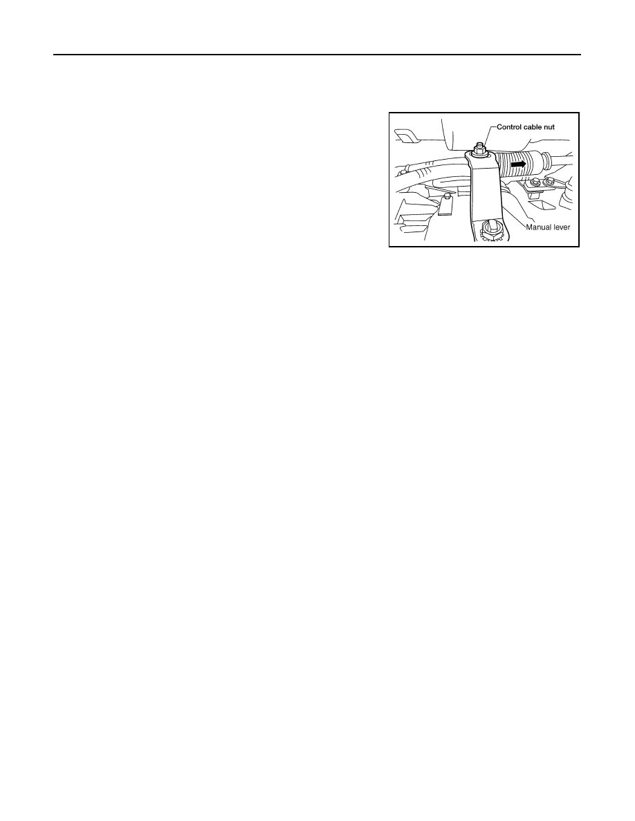
1. Loosen nut of control cable.
2. Place the manual lever and shift selector in “P” position.
3. Push the control cable in the direction shown with a force of 9.8

N (1kg, 2.2 lb), and release it. This is in the natural state, tighten

control cable nut to specifications.

Checking of A/T Position

INFOID:0000000006159449

With the shift selector in the “P” position, turn the ignition switch to the ON position with the engine OFF.

Confirm that the following conditions apply.

• The shift selector can be shifted from the “P” position only when the brake pedal is depressed.

• The shift selector stops at each position with the feel of engagement when it is moved through all the posi-

tions.

• There is no excessive effort, sticking, noise or rattle.

• The actual position of the shift selector matches the position shown by the shift position indicator and the A/

T body.

• The back-up lamps illuminate only when the shift selector is placed in the “R” position.

• The back-up lamps do not illuminate when the shift selector is pushed against the “R” position when in the

“P” or “N” position. 

• The engine can only be started with the shift selector in the “P” and “N” positions.

• The A/T is locked completely when in the “P” position.

Control cable nut

: 14.5 N·m (1.5 kg-m, 11 ft-lb)

SCIA6532E

SHIFT CONTROL SYSTEM

TM-185

< REMOVAL AND INSTALLATION >

C

E

F

G

H

I

J

K

L

M

A

B

TM

N

O

P

REMOVAL AND INSTALLATION

SHIFT CONTROL SYSTEM

A/T Shift Selector Removal and Installation

INFOID:0000000006159450

Floor shift models

LCIA0348E

1.

Shift selector handle

2.

A/T finisher

3.

A/T shift selector assembly

4.

Position lamp

5.

A/T control cable

6.

Lock plate

TM-186

< REMOVAL AND INSTALLATION >

SHIFT CONTROL SYSTEM

Column shift models

REMOVAL

Floor shift

1. Remove negative battery terminal. Refer to 

PG-76, "Removal and Installation"

.

2. Remove A/T finisher. Refer to 

IP-18, "Removal and Installation"

.

3. Disconnect A/T shift selector harness connector.
4. Disconnect A/T control cable.
5. Remove A/T shift selector assembly.

Column shift

1. Remove the steering column. Refer to 

ST-12, "Removal and Installation"

.

2. Remove the A/T control cable lock plate clip and remove the A/T

control cable from column shifter pin. 

3. Remove the A/T shift selector.

INSTALLATION

Installation is in reverse order of removal.

• After installation is completed, be sure to check A/T position. Refer to 

TM-187

. Adjust if necessary. Refer to

TM-187

.

AWDIA0782ZZ

1.

A/T shift selector

2.

A/T control cable

3.

A/T control cable lock plate clip

LCIA0343E

SHIFT CONTROL SYSTEM

TM-187

< REMOVAL AND INSTALLATION >

C

E

F

G

H

I

J

K

L

M

A

B

TM

N

O

P

Adjustment of A/T Position

INFOID:0000000006159451

1. Loosen nut of A/T control cable.
2. Place transmission range switch and shift selector in “P” posi-

tion.

3. After pushing the A/T control cable in the direction shown with a

force of 9.8 N·m (1kg-m, 2.2 lb-ft), release it. This is in the natu-

ral state, tighten A/T control cable nut to specifications.

Checking of A/T Position

INFOID:0000000006159452

NOTE:

Following procedure will cover both column and floor shift selectors.
1. Place shift selector in “P” position, and turn ignition switch ON

(engine stop).

2. Make sure shift selector can be shifted to other than “P” position

when brake pedal is depressed. Also make sure shift selector

can be shifted from “P” position only when brake pedal is

depressed.

3. Move the shift selector and check for excessive effort, sticking,

noise or rattle.

4. Confirm the shift selector stops at each position with the feel of

engagement when it is moved through all the positions. Check

whether or not the actual position the shift selector is in matches

the position shown by the shift position indicator and the trans-

mission body.

5. The method of operating the shift selector to individual positions

correctly should be as shown.

6. Confirm the back-up lamps illuminate only when shift selector is

placed in the “R” position. Confirm the back-up lamps does not

illuminate when shift selector is pushed against “R” position in

the “P” or “N” position.

7. Confirm the engine can only be started with the shift selector in

the “P” and “N” positions.

8. Make sure transmission is locked completely in “P” position.

A/T control cable 
nut

: 14.5 N·m (1.5 kg-m, 11 ft-lb)

LCIA0345E

LCIA0325E

LCIA0347E


Content   ..  947  948  949  950   ..