Nissan Titan A60. Manual - part 947


  Index      Nissan     Nissan Titan A60 (2011 year) - Service and Repair Manual


Search            


Content   ..  945  946  947  948   ..


Nissan Titan A60. Manual - part 947


TM-176

< PERIODIC MAINTENANCE >

STALL TEST

4. Engine start, apply foot brake, and place selector lever in “D”

position.

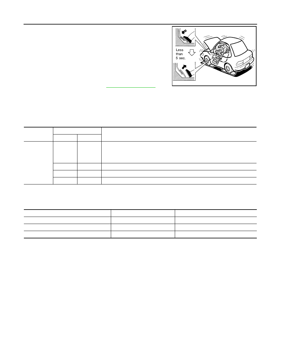
5. While holding down the foot brake, gradually press down the

accelerator pedal.

6. Quickly read off the stall speed, then quickly remove your foot

from the accelerator pedal.

CAUTION:

Do not hold down the accelerator pedal for more than 5 sec-

onds during this test.

7. Move the selector lever to the “N” position.
8. Cool down the ATF.

CAUTION:

Run the engine at idle for at least one minute.

Judgment of Stall Test

O: Stall speed within standard value position
H: Stall speed higher than standard value
L: Stall speed lower than standard value

Stall test standard value position

Stall speed

: Refer to 

TM-284, "Stall Speed"

.

SAT514G

Selector lever position

Expected problem location

D

R

Stall rotation 

H

O

• Forward brake
• Forward one-way clutch
• 1st one-way clutch
• 3rd one-way clutch

O

H

• Reverse brake 

L

L

• Engine and torque converter one-way clutch

H

H

•  Line pressure low

Does not shift-up D position 1 

→ 2

Slipping in 2GR, 3GR, 4GR

Direct clutch slippage

Does not shift-up D position 2 

→ 3

Slipping in 3GR, 4GR, 5GR

High and low reverse clutch slippage

Does not shift-up D position 3 

→ 4

Slipping in 4GR, 5GR

Input clutch slippage

Does not shift-up D position 4 

→ 5

Slipping in 5GR

Front brake slippage

LINE PRESSURE TEST

TM-177

< PERIODIC MAINTENANCE >

C

E

F

G

H

I

J

K

L

M

A

B

TM

N

O

P

LINE PRESSURE TEST

Inspection and Judgment

INFOID:0000000006159441

LINE PRESSURE TEST 

Line Pressure Test Port

Line Pressure Test Procedure

1. Inspect the amount of engine oil and replenish if necessary.
2. Drive the car for about 10 minutes to warm it up so that the ATF reaches in range of 50 to 80

°C (122 to

176

°F), then inspect the amount of ATF and replenish if necessary.

NOTE:

The automatic fluid temperature rises in range of 50 to 80

°C (122 to 176°F) during 10 minutes of

driving.

3. After warming up remove the oil pressure detection plug and

install the Tool.

CAUTION:

When using the oil pressure gauge, be sure to use the O-

ring attached to the oil pressure detection plug.

4. Securely engage the parking brake so that the tires do not turn.

SCIA2187E

SCIA5309E

SCIA1224E

TM-178

< PERIODIC MAINTENANCE >

LINE PRESSURE TEST

5. Start the engine, then measure the line pressure at both idle and

the stall speed.

CAUTION:

• Keep the brake pedal pressed all the way down during

measurement.

•  When measuring the line pressure at the stall speed, refer

to 

TM-74, "Description"

6. After the measurements are complete, install the oil pressure

detection plug and tighten to the regulation torque below.

CAUTION:

 Do not reuse the O-ring.

Judgment of Line Pressure Test

Line pressure

: Refer to 

TM-284, "Line Pressure"

.

Oil pressure detection 
plug

:7.3 N·m (0.74 kg-m, 65 in-lb)

SAT493G

Judgment Possible 

cause

Idle speed

Low for all positions 
(P, R, N, D)

Possible causes include malfunctions in the pressure supply system and low oil pump output.
For example
• Oil  pump  wear
• Pressure regulator valve or plug sticking or spring fatigue
• Oil strainer 

⇒ oil pump ⇒ pressure regulator valve passage oil leak

• Engine idle speed too low

Only low for a spe-
cific position

Possible causes include an oil pressure leak in a passage or device related to the position after 
the pressure is distributed by the manual valve.

High

Possible causes include a sensor malfunction or malfunction in the line pressure adjustment func-
tion.
For example
• Accelerator pedal position signal malfunction
• ATF temperature sensor malfunction
• Line pressure solenoid malfunction (sticking in “OFF” state, filter clog, cut line)
• Pressure regulator valve or plug sticking

Stall speed

Oil pressure does 
not rise higher than 
the oil pressure for 
idle.

Possible causes include a sensor malfunction or malfunction in the pressure adjustment function.
For example
• Accelerator pedal position signal malfunction
• TCM breakdown
• Line pressure solenoid malfunction (shorting, sticking in“ ON” state)
• Pressure regulator valve or plug sticking
• Pilot valve sticking or pilot filter clogged

The pressure rises, 
but does not enter 
the standard posi-
tion.

Possible causes include malfunctions in the pressure supply system and malfunction in the pres-
sure adjustment function.
 For example
• Accelerator pedal position signal malfunction
• Line pressure solenoid malfunction (sticking, filter clog)
• Pressure regulator valve or plug sticking
• Pilot valve sticking or pilot filter clogged

Only low for a spe-
cific position

Possible causes include an oil pressure leak in a passage or device related to the position after 
the pressure is distributed by the manual valve.

ROAD TEST

TM-179

< PERIODIC MAINTENANCE >

C

E

F

G

H

I

J

K

L

M

A

B

TM

N

O

P

ROAD TEST

Description

INFOID:0000000006159442

ROAD TEST 

• The road test inspects overall performance of the A/T and analyzes possible malfunction causes.

• The road test is carried out in the following three stages.

1. Check before engine is started. Refer to 

TM-179, "Check Before Engine Is Started"

2. Check at idle. Refer to 

TM-179, "Check At Idle"

.

3. Cruise test

• Inspect all the items from Part 1 to Part 3. Refer to 

TM-180, "Cruise Test - Part 1"

TM-182, "Cruise Test

- Part 2"

TM-182, "Cruise Test - Part 3"

• Before beginning the road test, check the test procedure and inspection items.

• Test all inspection items until the symptom is uncovered. Diagnose NG items when all road tests are com-

plete.

Check Before Engine Is Started

INFOID:0000000006159443

1.

CHECK AT CHECK INDICATOR LAMP

1. Park vehicle on level surface.

2. Move selector lever to “P” position.

3. Turn ignition switch to “OFF” position and wait at least 10 seconds.

4. Turn ignition switch to “ON” position. (Do not start engine.)
Does AT CHECK indicator lamp light up for about 2 seconds?

YES

>> 1. Turn ignition switch to “OFF” position.

2. Carry out the self-diagnostics and record all NG items on the diagnostics worksheet. Refer to

TM-36, "CONSULT-III Function (TRANSMISSION)"

.

3. Go to 

TM-179, "Check At Idle"

.

NO

>> Stop the road test and go to 

TM-139, "Symptom Table"

Check At Idle

INFOID:0000000006159444

1.

CHECK STARTING THE ENGINE

1. Park vehicle on level surface.

2. Move selector lever to “P” or “N” position.

3. Turn ignition switch to “OFF” position.

4. Turn ignition switch to “START” position.
Does the engine start?

YES

>> GO TO 2.

NO

>> Stop the road test and go to 

TM-139, "Symptom Table"

.

2.

CHECK STARTING THE ENGINE

1. Turn ignition switch to “ON” position.

2. Move selector lever in “D”,“4”, “3”, “2”, “1” or “R” position.

3. Turn ignition switch to “START” position.
Does the engine start in either position?

YES

>> Stop the road test and go to 

TM-139, "Symptom Table"

.

NO

>> GO TO 3.

3.

CHECK “P” POSITION FUNCTIONS

1. Move selector lever to “P” position.

2. Turn ignition switch to “OFF” position.

3. Release the parking brake.

4. Push the vehicle forward or backward.

5. Engage the parking brake.


Content   ..  945  946  947  948   ..