Nissan Titan A60. Manual - part 539


  Index      Nissan     Nissan Titan A60 (2011 year) - Service and Repair Manual


Search            


Content   ..  537  538  539  540   ..


Nissan Titan A60. Manual - part 539


FL-12

< UNIT REMOVAL AND INSTALLATION >

FUEL LEVEL SENSOR UNIT, FUEL FILTER AND FUEL PUMP ASSEMBLY

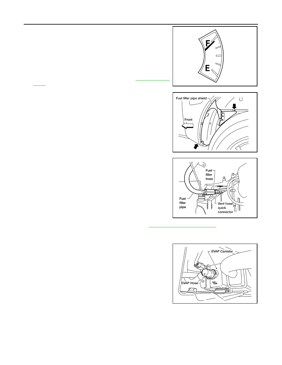
2. Check the fuel level on level gauge. If the fuel gauge indicates

more than the level as shown (full or almost full), drain the fuel

from the fuel tank until the fuel gauge indicates the level as

shown, or less.

• If the fuel pump does not operate, use the following procedure

to drain the fuel to the specified level.

a. Insert a suitable hose of less than 15 mm (0.59 in) diameter into

the fuel filler pipe through the fuel filler opening to drain the fuel

from fuel filler pipe.

b. Remove the LH rear wheel and tire. Refer to 

WT-46, "Adjust-

ment"

.

c.

Remove the fuel filler pipe shield.

d. Disconnect the fuel filler hose from the fuel filler pipe and dis-

connect the vent hose quick connector.

e. Insert a suitable hose into the fuel tank through the fuel filler

hose to drain the fuel from the fuel tank.

3. Release the fuel pressure from the fuel lines. Refer to 

EC-473, "Fuel Pressure Check"

.

4. Disconnect the battery negative terminal.
5. Remove the three nuts and remove fuel line pump protector.
6. Disconnect the EVAP hose at the EVAP canister.

WBIA0390E

LBIA0437E

LBIA0386E

LBIA0405E

FUEL LEVEL SENSOR UNIT, FUEL FILTER AND FUEL PUMP ASSEMBLY

FL-13

< UNIT REMOVAL AND INSTALLATION >

C

D

E

F

G

H

I

J

K

L

M

A

FL

N

P

O

7. Disconnect the fuel level sensor, fuel filter, and fuel pump

assembly electrical connector and the fuel feed hose.

Disconnect the quick connector as follows:

• Hold the sides of the connector, push in tabs and pull out the

tube.

• If the connector and the tube are stuck together, push and pull

several times until they start to move. Then disconnect them

by pulling.

CAUTION:

• The quick connector can be disconnected when the tabs

are completely depressed. Do not twist the quick connec-

tor more than necessary.

• Do not use any tools to disconnect the quick connector.

• Keep the resin tube away from heat. Be especially careful

when welding near the tube.

• Prevent any acid liquids such as battery electrolyte, from

getting on the resin tube.

• Do not bend or twist the resin tube during connection. 

• Do not remove the remaining retainer on the hard tube (or

the equivalent) except when the resin tube or the retainer

is replaced.

• When the resin tube or hard tube, or the equivalent, is 

replaced, also replace the retainer with a new one (white

colored retainer).

LBIA0406E

SFE562A

PBIC1268E

FL-14

< UNIT REMOVAL AND INSTALLATION >

FUEL LEVEL SENSOR UNIT, FUEL FILTER AND FUEL PUMP ASSEMBLY

• To keep the quick connector clean and to avoid damage

and contamination from foreign materials, cover the quick

connector with plastic bags or suitable material as shown.      

8. Remove the four bolts and remove the fuel tank shield using power tool.
9. Remove the fuel tank strap bolts while supporting the fuel tank

with a suitable lift jack.

10. Lower the fuel tank using a suitable lift jack and remove it from

the vehicle to access the fuel level sensor, fuel filter, and fuel

pump assembly.

11. Remove the lock ring using Tool as shown.

12. Remove the fuel level sensor, fuel filter, and fuel pump assem-

bly. Remove and discard the O-ring.

CAUTION:

• Do not bend the float arm during removal.

• Avoid impacts such as dropping when handling the com-

ponents.

• Discard the O-ring, do not reuse.

INSTALLATION

Installation is in the reverse order of removal.

• For installation, use a new fuel level sensor, fuel filter, and fuel pump assembly O-ring.

• Connect the quick connector as follows:

- Check the connection for any damage or foreign materials.

- Align the connector with the pipe, then insert the connector straight into the pipe until a click is heard.

- After connecting the quick connector, make sure that the connec-

tion is secure by checking as follows:

- Pull the tube and the connector to make sure they are securely

connected.

- Visually inspect the connector to make sure the two retainer tabs

are securely connected.

INSPECTION AFTER INSTALLATION

1. Turn the ignition switch ON but do not start engine, then check the fuel pipes and hose connections for

leaks while applying fuel pressure to the system.

PBIC0163E

LBIA0387E

Tool number

:  — (J-46536)

LBIA0407E

PBIC1653E

FUEL LEVEL SENSOR UNIT, FUEL FILTER AND FUEL PUMP ASSEMBLY

FL-15

< UNIT REMOVAL AND INSTALLATION >

C

D

E

F

G

H

I

J

K

L

M

A

FL

N

P

O

2. Start the engine and rev it above idle speed, then check that there are no fuel leaks at any of the fuel pipe

and hose connections.


Content   ..  537  538  539  540   ..