Nissan Titan A60. Manual - part 538


  Index      Nissan     Nissan Titan A60 (2011 year) - Service and Repair Manual


Search            


Content   ..  536  537  538  539   ..


Nissan Titan A60. Manual - part 538


FL-8

< UNIT REMOVAL AND INSTALLATION >

FUEL TANK

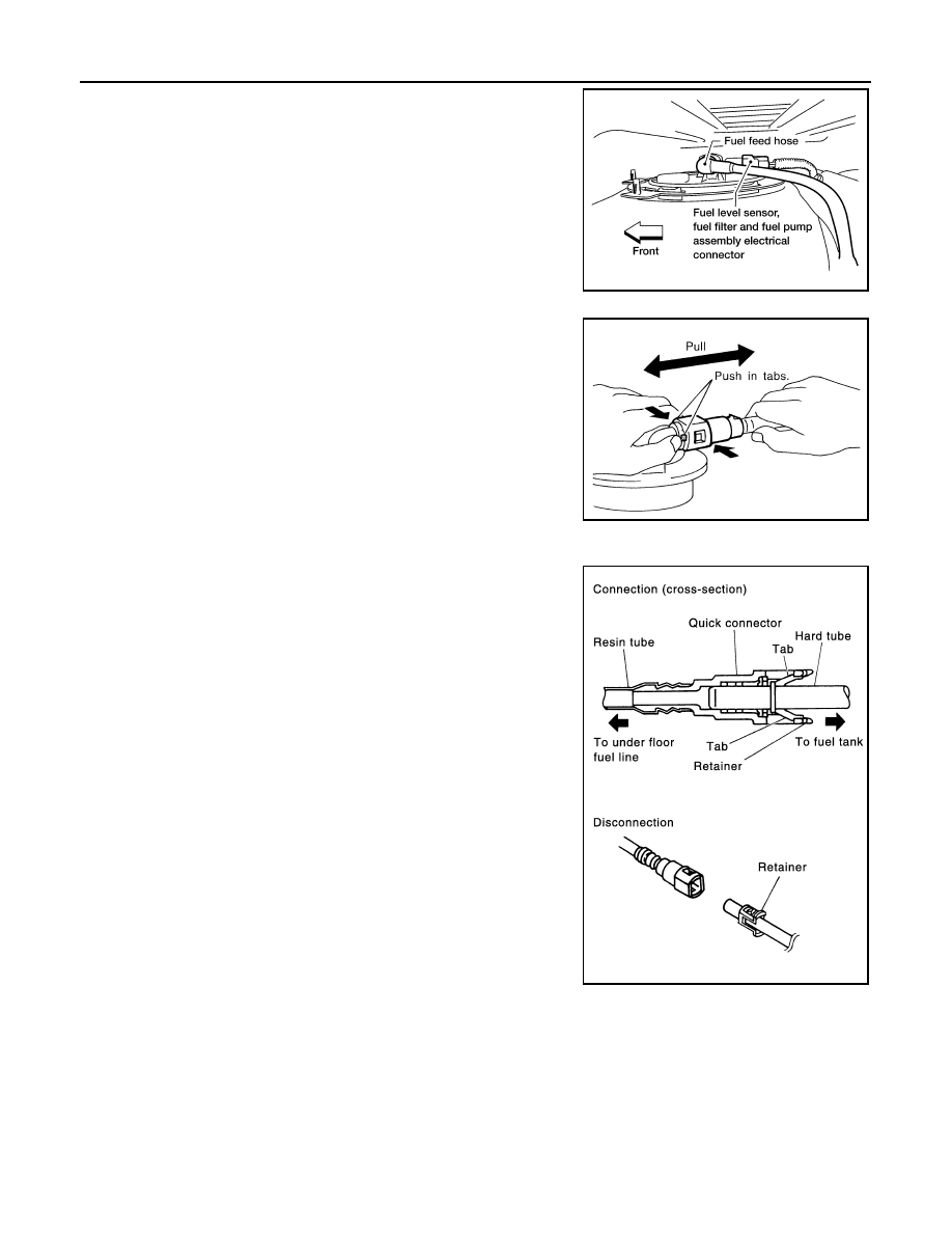
7. Disconnect the fuel level sensor, fuel filter, and fuel pump

assembly electrical connector, and the fuel feed hose.

Disconnect the quick connector as follows:

• Hold the sides of the connector, push in tabs and pull out the

tube.

• If the connector and the tube are stuck together, push and pull

several times until they start to move. Then disconnect them

by pulling.

CAUTION:

• The quick connector can be disconnected when the tabs

are completely depressed. Do not twist the quick connec-

tor more than necessary.

• Do not use any tools to disconnect the quick connector.

• Keep the resin tube away from heat. Be especially careful

when welding near the tube.

• Prevent any acid liquids such as battery electrolyte, from

getting on the resin tube.

• Do not bend or twist the resin tube during connection. 

• Do not remove the remaining retainer on the hard tube (or

the equivalent) except when the resin tube or the retainer

is replaced.

• When the resin tube or hard tube, or the equivalent, is 

replaced, also replace the retainer with a new one (white

colored retainer).

LBIA0406E

SFE562A

PBIC1268E

FUEL TANK

FL-9

< UNIT REMOVAL AND INSTALLATION >

C

D

E

F

G

H

I

J

K

L

M

A

FL

N

P

O

• To keep the quick connector clean and to avoid damage

and contamination from foreign materials, cover the quick

connector with plastic bags or suitable material as shown.      

8. Remove the four bolts and remove the fuel tank shield using power tool.
9. Disconnect fuel filler hose at the fuel tank side.
10. Remove the fuel tank strap bolts while supporting the fuel tank

with a suitable lift jack.

11. Lower the fuel tank using a suitable lift jack and remove it from

the vehicle.

12. If necessary, remove the lock ring using Tool as shown.

13. If necessary, remove the fuel level sensor, fuel filter, and fuel

pump assembly. Discard the O-ring.

CAUTION:

• Do not bend the float arm during removal.

• Avoid impacts such as dropping when handling the com-

ponents.

• Discard the O-ring, do not reuse.

INSTALLATION

Installation is in the reverse order of removal.

• For installation, use a new fuel level sensor, fuel filter, and fuel pump assembly O-ring.

• Connect the quick connector as follows:

- Check the connection for any damage or foreign materials.

- Align the connector with the pipe, then insert the connector straight into the pipe until a click is heard.

- After connecting the quick connector, make sure that the connec-

tion is secure by checking as follows:

- Pull the tube and the connector to make sure they are securely

connected.

- Visually inspect the connector to make sure the two retainer tabs

are securely connected.

INSPECTION AFTER INSTALLATION

1. Turn the ignition switch ON but do not start engine, then check the fuel pipe and hose connections for

leaks while applying fuel pressure to the system.

PBIC0163E

LBIA0387E

Tool number

:  — (J-46536)

LBIA0407E

PBIC1653E

FL-10

< UNIT REMOVAL AND INSTALLATION >

FUEL TANK

2. Start the engine and rev it above idle speed, then check that there are no fuel leaks at any of the fuel pipe

and hose connections.

FUEL LEVEL SENSOR UNIT, FUEL FILTER AND FUEL PUMP ASSEMBLY

FL-11

< UNIT REMOVAL AND INSTALLATION >

C

D

E

F

G

H

I

J

K

L

M

A

FL

N

P

O

FUEL LEVEL SENSOR UNIT, FUEL FILTER AND FUEL PUMP ASSEMBLY

Removal and Installation

INFOID:0000000006164623

REMOVAL

WARNING:

Follow the “General Precautions” before working on the fuel system. Refer to 

FL-3, "General Precau-

tion"

.

1. Remove the fuel filler cap to release the pressure from inside the fuel tank.

1.

Fuel line pump protector

2.

Lock ring

3.

Fuel level sensor, fuel filter, and fuel 
pump assembly

4.

Fuel tank

5.

Fuel tank protector

6.

Fuel tank protector clips

7.

Fuel tank straps

8.

O-ring

9.

Fuel filler hose

10. Fuel filler pipe

11.

Fuel filler hose grommet

12. Fuel filler cap

13. Fuel tank shield

AWBIA0882GB


Content   ..  536  537  538  539   ..