Nissan Titan A60. Manual - part 467


  Index      Nissan     Nissan Titan A60 (2011 year) - Service and Repair Manual


Search            


Content   ..  465  466  467  468   ..


Nissan Titan A60. Manual - part 467


TIMING CHAIN

EM-53

< REMOVAL AND INSTALLATION >

C

D

E

F

G

H

I

J

K

L

M

A

EM

N

P

O

Removal and Installation

INFOID:0000000006628784

NOTE:

• To remove timing chain and associated parts, start with those on the LH bank. The procedure for removing

parts on the RH bank is omitted because it is the same as that for removal on the LH bank.

• To install timing chain and associated parts, start with those on the RH bank. The procedure for installing

parts on the LH bank is omitted because it is the same as that for installation on the RH bank.

REMOVAL

1. Remove the timing chain cover. Refer to 

EM-48, "Removal and Installation"

.

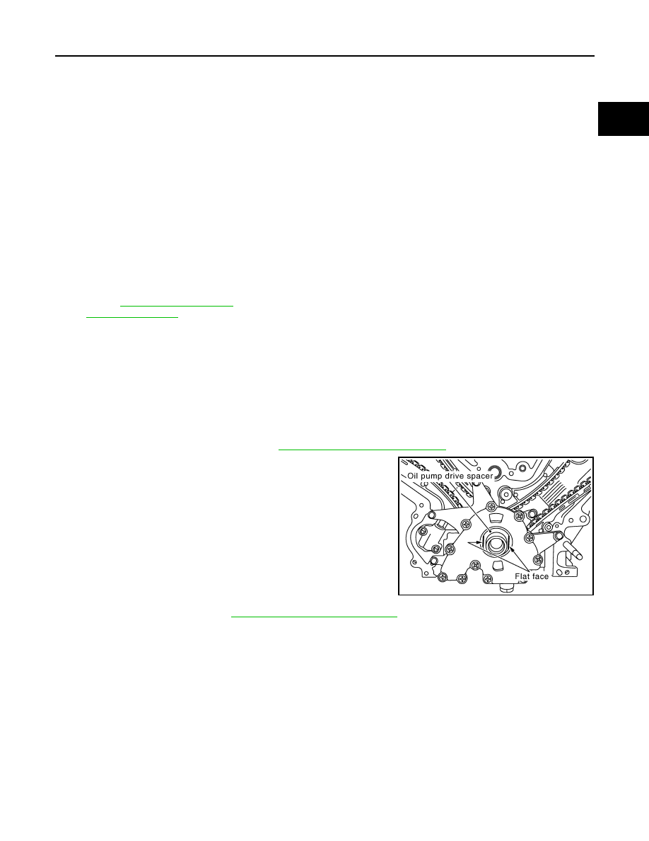
2. Remove the oil pump drive spacer.

• Hold and remove the flat space of the oil pump drive spacer by

pulling it forward. 

3. Remove the oil pump. Refer to 

LU-14, "Removal and Installation"

.

4. Remove the chain tensioner on the LH bank using the following steps.

NOTE:

To remove the timing chain and associated parts, start with those on the LH bank. The procedure for

removing parts on the RH bank is omitted because it is the same as that for the LH bank. 

1.

Camshaft sprocket LH bank EXH

2.

Camshaft sprocket LH bank INT 
(VTC)

3.

Camshaft sprocket RH bank INT 
(VTC)

4.

Camshaft sprocket RH bank EXH

5.

Front cover

6.

Intake valve timing control solenoid 
valve (RH)

7.

Intake valve timing control solenoid 
valve cover (RH)

8.

Intake valve timing control position 
sensor (RH)

9.

Intake valve timing control position 
sensor (LH)

10. Intake valve timing control solenoid 

valve cover (LH)

11.

Camshaft position sensor (PHASE)

12

Crankshaft pulley bolt

13. Crankshaft pulley

14.

Chain tensioner cover

15.

Front oil seal

16. Intake valve timing control solenoid 

valve (LH)

17.

O-ring

18.

Timing chain tension guide RH bank

19. Timing chain slack guide (RH)

20.

Timing chain RH bank

21.

Timing chain LH bank

22. Chain tensioner (RH)

23.

Timing chain slack guide LH bank

24.

Timing chain tension guide LH bank

25. Chain tensioner (LH)

26.

O-ring

27.

Bracket

28. Oil pump drive spacer

29.

Oil pump assembly

30.

Crankshaft sprocket

A.

To crankshaft

B.

To camshaft LH bank EXH

C.

To camshaft LH bank INT (VTC)

D.

To camshaft RH bank INT (VTC)

E.

To camshaft RH bank EXH

F.

Apply sealant to mating side

G.

Refer to 

EM-69, "Removal and Instal-

lation of Front Oil Seal"

KBIA2512E

EM-54

< REMOVAL AND INSTALLATION >

TIMING CHAIN

a. Squeeze the return-proof clip ends using suitable tool and push

the plunger into the tensioner body.

b. Secure the plunger using stopper pin.

• Stopper pin is made from hard wire approximately 1 mm (0.04

in) in diameter.

c.

Remove the bolts and chain tensioner.

WARNING:

Plunger, spring, and spring seat pop out when (squeezing)

return-proof clip without holding plunger head. It may

cause serious injuries. Always hold plunger head when

removing.

NOTE:

• Stop the plunger in the fully extended position by using the

return-proof clip (1) if the stopper pin is removed.

• Push the plunger (2) into the tensioner body while squeezing

the return-proof clip (1). Secure it using stopper pin (3).

5. Remove the timing chain tension guide and timing chain slack guide.
6. Remove the timing chain and crankshaft sprocket.
7. Loosen the camshaft sprocket bolts as shown and remove the

camshaft sprocket.

CAUTION:

To avoid interference between valves and pistons, do not

turn crankshaft or camshaft when timing chain is discon-

nected.

8. Repeat the same procedure to remove the RH timing chain and

associated parts.

INSPECTION AFTER REMOVAL

Check for cracks and any excessive wear at link plates. Replace

chain if necessary.

• In the same way as for the LH bank, inspect the timing chain and

associated parts on the RH bank.

INSTALLATION

KBIA2479E

KBIA2483E

WBIA0799E

PBIC0282E

TIMING CHAIN

EM-55

< REMOVAL AND INSTALLATION >

C

D

E

F

G

H

I

J

K

L

M

A

EM

N

P

O

NOTE:

• The illustration above shows the relationship between the mating mark on each timing chain and that of the

corresponding sprocket, with the components installed.

• To install the timing chain and associated parts, start with those on the RH bank. The procedure for installing

parts on the LH bank is omitted because it is the same as that for installation on the RH bank.

1. Make sure the crankshaft key and RH bank camshaft dowel pin

and LH bank camshaft dowel pin are facing in the direction

shown.

1.

Camshaft sprocket RH bank INT 
(VTC) 

2.

Camshaft sprocket RH bank EXH

3.

Camshaft dowel pin RH bank 

4.

Timing chain RH bank

5.

Timing chain slack guide RH bank

6.

Chain tensioner RH

7.

Crankshaft sprocket

8.

Crankshaft key

9.

Timing chain tension guide LH bank

10. Timing chain LH bank

11. Camshaft dowel pin LH bank

12. Camshaft sprocket LH bank EXH

13. Camshaft sprocket LH bank INT 

(VTC)

14. Chain tensioner LH

15. Timing chain tension guide RH bank

16. Timing chain slack guide LH bank

A.

LH bank

B.

RH bank

C.

Alignment mark (Link color: copper) D.

Alignment mark (Link color: copper) E.

Alignment mark (Identification mark)

F.

Alignment mark for LH bank (Notch) G.

Alignment mark for LH bank (Link 
color: zinc yellow)

H.

Alignment mark for RH bank (Link 
color: zinc yellow)

J.

Alignment mark (Link color: copper) K.

Alignment mark (Identification mark) L.

Alignment mark (Identification mark)

M

Alignment mark (Link color: copper) N.

Alignment mark (Identification mark)

AWBIA0150ZZ

SBIA0356E

EM-56

< REMOVAL AND INSTALLATION >

TIMING CHAIN

2. Install the camshaft sprockets.

• Install the camshaft sprocket INT (VTC) (A) and camshaft

sprockets EXH (B) by selectively using the groove of the

dowel pin according to the bank. (Common part used for both

exhaust banks.) 

NOTE:

Use the groove marked "R" for RH bank and "L" for LH bank.

• Lock the hexagonal part of the camshaft in the same way as

for removal, and tighten the bolts.

3. Install the crankshaft sprockets for both banks.

• Install LH bank crankshaft sprocket (B) and RH bank crank-

shaft sprocket (C) so that their flange side (A) (the larger diam-

eter side without teeth) faces in the direction shown.

NOTE:

The same parts are used but facing directions are different.

4. Install the timing chains and associated parts.

• Align the alignment mark on each sprocket and the timing chain for installation.

CAUTION:

• Before installing timing chain tensioner, it is possible to change the position of alignment mark

on timing chain and each sprocket. After the alignment marks are aligned, keep them aligned

by holding them by hand.

• Install the slack guides and tension guides onto the correct side by checking the identification mark on

the surface.

• Install the timing chain tensioner with the plunger locked in with the stopper pin.

CAUTION:

• Before and after the installation of the timing chain tensioner, make sure that the alignment

mark on the timing chain is not out of alignment.

• After installing the timing chain tensioner, remove the stopper pin to release the tensioner.

Make sure the tensioner is released.

• To avoid chain-link skipping of the timing chain, do not move crankshaft or camshafts until the

front cover is installed.

5. In the same way as for the RH bank, install the timing chain and associated parts on the LH bank.
6. Install the oil pump. 
7. Install the oil pump drive spacer as follows:

• Install so that the front mark on the front edge of the oil pump

drive spacer faces the front of the engine.

• Insert the oil pump drive spacer according to the directions of

the crankshaft key and the two flat surfaces of the oil pump

inner rotor. 

• If the positional relationship does not allow the insertion, rotate

the oil pump inner rotor to allow the oil pump drive spacer to

be inserted.

AWBIA0151ZZ

WBIA0701E

KBIA2490E


Content   ..  465  466  467  468   ..