Nissan Titan A60. Manual - part 464
FUEL INJECTOR AND FUEL TUBE
EM-41
< REMOVAL AND INSTALLATION >
C
D
E
F
G
H
I
J
K
L
M
A
EM
N
P
O
FUEL INJECTOR AND FUEL TUBE
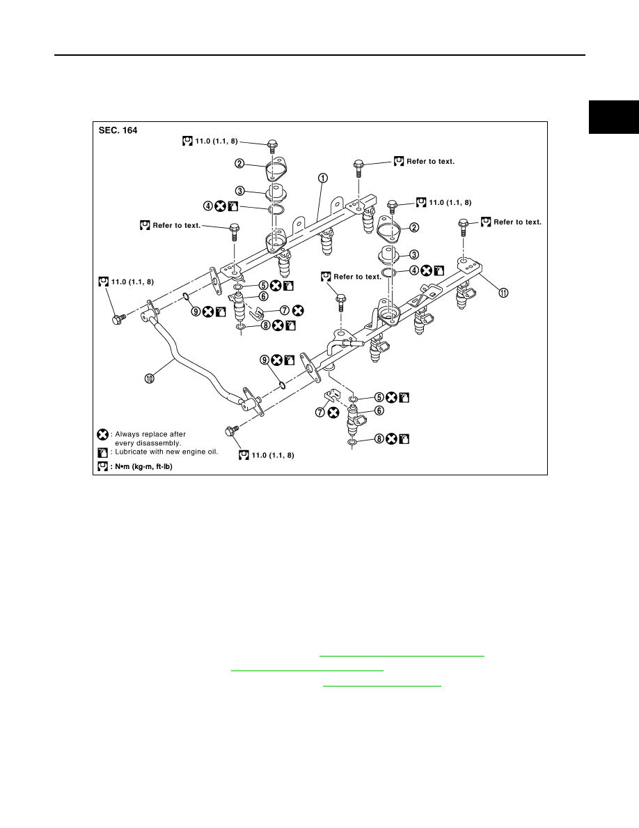
Exploded View
INFOID:0000000006179401
Removal and Installation
INFOID:0000000006179402
CAUTION:
Do not remove or disassemble parts unless instructed as shown.
REMOVAL
1. Disconnect the negative battery terminal. Refer to
PG-76, "Removal and Installation"
2. Release fuel pressure. Refer to
.
3. Remove air duct and resonator assembly. Refer to
4. Disconnect fuel injector harness connectors.
5. Disconnect EVAP canister purge control solenoid valve.
6. Disconnect fuel hose assembly from fuel tube (RH bank and LH bank).
CAUTION:
• While hoses are disconnected, plug them to prevent fuel from draining.
• Do not separate fuel connector and fuel hose.
7. Remove fuel injectors with fuel tube assembly.
1.
Fuel tube (RH bank)
2.
Cap
3.
Fuel damper
4.
O-ring
5.
O-ring (Standard model: Blue)
(FFV model: Black)
6.
Fuel injector
7.
Clip
8.
O-ring (Standard model: Brown)
(FFV model: Green)
9.
O-ring
10. Fuel hose assembly
11. Fuel tube (LH bank)
KBIA2472E