Nissan Titan A60. Manual - part 175


  Index      Nissan     Nissan Titan A60 (2011 year) - Service and Repair Manual


Search            


Content   ..  173  174  175  176   ..


Nissan Titan A60. Manual - part 175


BRC-78

< DTC/CIRCUIT DIAGNOSIS >

[VDC/TCS/ABS]

VDC OFF SWITCH

VDC OFF SWITCH

Description

INFOID:0000000006165928

VDC OFF switch can deactivate (turn OFF) the VDC/TCS function by pressing the VDC OFF switch.

Component Function Check

INFOID:0000000006165929

1.

CHECK VDC OFF SWITCH OPERATION

Turn ON/OFF the VDC OFF switch and check that the VDC OFF indicator lamp in the combination meter turns

ON/OFF correctly.

Is the inspection result normal?

YES

>> Inspection End

NO

>> Go to diagnosis procedure. Refer to 

BRC-78, "Diagnosis Procedure"

.

Diagnosis Procedure

INFOID:0000000006165930

Regarding Wiring Diagram information, refer to 

BRC-92, "Wiring Diagram"

.

1.

CHECK VDC OFF SWITCH

Perform the VDC OFF switch component inspection. Refer to 

BRC-79, "Component Inspection"

.

Is the inspection result normal?

YES

>> GO TO 2

NO

>> Replace VDC OFF switch.

2.

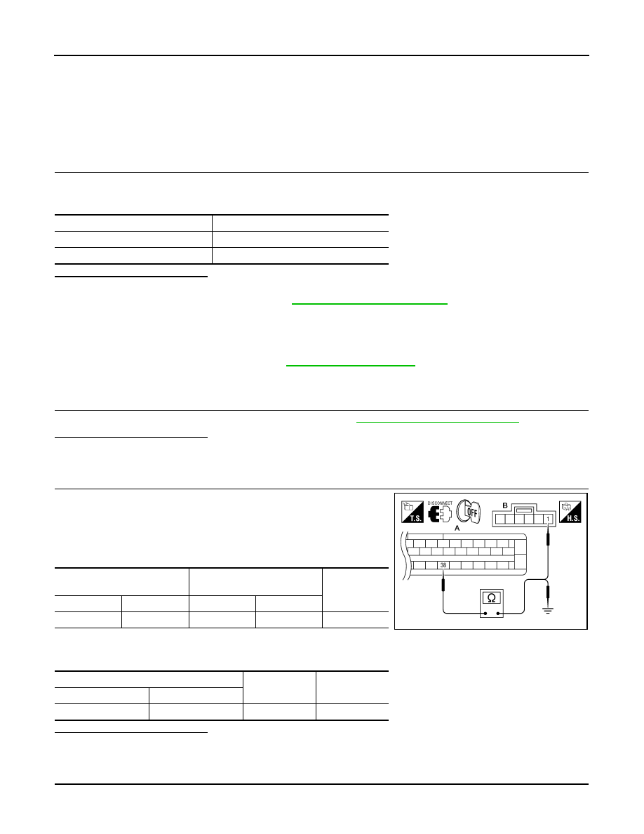
CHECK VDC OFF SWITCH HARNESS

1. Disconnect ABS actuator and electric unit (control unit) connec-

tor.

2. Check continuity between ABS actuator and electric unit (control

unit) connector E125 (A) terminal 38 and VDC OFF switch con-

nector M148 (B) terminal 1.

3. Check continuity between ABS actuator and electric unit (control

unit) connector E125 (A) terminal 38 and ground.

Is the inspection result normal?

YES

>> GO TO 3

NO

>> Repair or replace harness.

3.

CHECK VDC OFF SWITCH GROUND

Condition

VDC OFF indicator lamp illumination status

VDC OFF switch: ON

ON

VDC OFF switch: OFF

OFF

ABS actuator and electric unit 

(control unit)

VDC OFF switch

Continuity

Connector

Terminal

Connector

Terminal

A: E125

38

B: M148

1

Yes

ABS actuator and electric unit (control unit)

Continuity

Connector

Terminal

A: E125

38

Ground

No

AWFIA0430ZZ

VDC OFF SWITCH

BRC-79

< DTC/CIRCUIT DIAGNOSIS >

[VDC/TCS/ABS]

C

D

E

G

H

I

J

K

L

M

A

B

BRC

N

O

P

Check continuity between VDC OFF switch connector M148 terminal

2 and ground.

Is the inspection result normal?

YES

>> GO TO 4

NO

>> Repair or replace harness.

4.

CHECK COMBINATION METER

Check if the indication and operation of combination meter are normal. Refer to 

MWI-27, "Diagnosis Descrip-

tion"

.

Is the inspection result normal?

YES

>> Replace ABS actuator and electric unit (control unit). Refer to 

BRC-116, "Removal and Installa-

tion"

.

NO

>> Replace combination meter. Refer to 

MWI-93, "Removal and Installation"

.

Component Inspection

INFOID:0000000006165931

1.

CHECK VDC OFF SWITCH

1. Turn ignition switch OFF.

2. Disconnect VDC OFF switch connector.

3. Check continuity between VDC OFF switch terminals.

Is the inspection result normal?

YES

>> Inspection End

NO

>> Replace VDC OFF switch.

Special Repair Requirement

INFOID:0000000006649004

1.

ADJUSTMENT OF STEERING ANGLE SENSOR NEUTRAL POSITION

Always perform neutral position adjustment for the steering angle sensor when replacing the ABS actuator

and electric unit (control unit). Refer to 

BRC-8, "ADJUSTMENT OF STEERING ANGLE SENSOR NEUTRAL

POSITION : Description"

.

>> GO TO 2

2.

CALIBRATION OF DECEL G SENSOR

Always perform calibration of decel G sensor when replacing the ABS actuator and electric unit (control unit).

Refer to 

BRC-9, "CALIBRATION OF DECEL G SENSOR : Description"

.

>> END

VDC OFF switch

Continuity

Connector

Terminal

M148

2

Ground

Yes

AWFIA0031ZZ

VDC OFF switch terminals

Condition

Continuity

− 2

When VDC OFF switch is pressed.

Yes

When VDC OFF switch is released.

No

AWFIA0446ZZ

BRC-80

< DTC/CIRCUIT DIAGNOSIS >

[VDC/TCS/ABS]

ABS WARNING LAMP

ABS WARNING LAMP

Description

INFOID:0000000006165933

×: ON –: OFF

Component Function Check

INFOID:0000000006165934

1.

CHECK ABS WARNING LAMP OPERATION

Check that the lamp illuminates for approximately 2 seconds after the ignition switch is turned ON.
Is the inspection result normal?

YES

>> Inspection End

NO

>> Go to diagnosis procedure. Refer to 

BRC-80, "Diagnosis Procedure"

.

Diagnosis Procedure

INFOID:0000000006165935

1.

CHECK SELF-DIAGNOSIS

Perform ABS actuator and electric unit (control unit) self-diagnosis. Refer to 

BRC-24, "CONSULT-III Function

(ABS)"

.

Is the inspection result normal?

YES

>> GO TO 2

NO

>> Check items displayed by self-diagnosis.

2.

CHECK COMBINATION METER

Check if the indication and operation of combination meter are normal. Refer to 

MWI-27, "Diagnosis Descrip-

tion"

.

Is the inspection result normal?

YES

>> Replace ABS actuator and electric unit (control unit). Refer to 

BRC-116, "Removal and Installa-

tion"

.

NO

>> Replace combination meter. Refer to 

MWI-93, "Removal and Installation"

.

Special Repair Requirement

INFOID:0000000006649005

1.

ADJUSTMENT OF STEERING ANGLE SENSOR NEUTRAL POSITION

Always perform neutral position adjustment for the steering angle sensor when replacing the ABS actuator

and electric unit (control unit). Refer to 

BRC-8, "ADJUSTMENT OF STEERING ANGLE SENSOR NEUTRAL

POSITION : Description"

.

>> GO TO 2

2.

CALIBRATION OF DECEL G SENSOR

Always perform calibration of decel G sensor when replacing the ABS actuator and electric unit (control unit).

Refer to 

BRC-9, "CALIBRATION OF DECEL G SENSOR : Description"

.

>> END

Condition

ABS warning lamp

Ignition switch OFF

For 2 seconds after turning ON ignition switch

×

2 seconds later after turning ON ignition switch

ABS function is malfunctioning.

×

EBD function is malfunctioning.

×

BRAKE WARNING LAMP

BRC-81

< DTC/CIRCUIT DIAGNOSIS >

[VDC/TCS/ABS]

C

D

E

G

H

I

J

K

L

M

A

B

BRC

N

O

P

BRAKE WARNING LAMP

Description

INFOID:0000000006165937

×: ON –: OFF

NOTE:
• 1: Brake warning lamp will turn on in case of parking brake operation (when switch is ON) or of brake fluid level switch operation

(when brake fluid is insufficient).

• 2: After starting engine, brake warning lamp is turned off.

Component Function Check

INFOID:0000000006165938

1.

BRAKE WARNING LAMP OPERATION CHECK

Check that the lamp illuminates after the ignition switch is turned ON, and turns OFF after the engine is

started.
Is the inspection result normal?

YES

>> Inspection End

NO

>> Go to diagnosis procedure. Refer to 

BRC-81, "Diagnosis Procedure"

.

Diagnosis Procedure

INFOID:0000000006165939

1.

CHECK SELF-DIAGNOSIS

Perform ABS actuator and electric unit (control unit) self-diagnosis. Refer to 

BRC-24, "CONSULT-III Function

(ABS)"

.

Is the inspection result normal?

YES

>> GO TO 2

NO

>> Check items displayed by self-diagnosis.

2.

CHECK COMBINATION METER

Check if the indication and operation of combination meter are normal. Refer to 

MWI-27, "Diagnosis Descrip-

tion"

.

Is the inspection result normal?

YES

>> Replace ABS actuator and electric unit (control unit). Refer to 

BRC-116, "Removal and Installa-

tion"

.

NO

>> Replace combination meter. Refer to 

MWI-93, "Removal and Installation"

.

Special Repair Requirement

INFOID:0000000006649006

1.

ADJUSTMENT OF STEERING ANGLE SENSOR NEUTRAL POSITION

Always perform neutral position adjustment for the steering angle sensor when replacing the ABS actuator

and electric unit (control unit). Refer to 

BRC-8, "ADJUSTMENT OF STEERING ANGLE SENSOR NEUTRAL

POSITION : Description"

.

>> GO TO 2

2.

CALIBRATION OF DECEL G SENSOR

Always perform calibration of decel G sensor when replacing the ABS actuator and electric unit (control unit).

Refer to 

BRC-9, "CALIBRATION OF DECEL G SENSOR : Description"

.

>> END

Condition

Brake warning lamp (Note 1)

Ignition switch OFF

Ignition switch ON

× (Note 2)

EBD function is malfunctioning.

×


Content   ..  173  174  175  176   ..