Nissan Titan A60. Manual - part 174
BRC-74
< DTC/CIRCUIT DIAGNOSIS >
[VDC/TCS/ABS]
C1179 ABS DELTA S SEN NG
C1179 ABS DELTA S SEN NG
Description
INFOID:0000000006165917
The active brake booster consists of a vacuum booster, an active booster control group and a delta stroke
sensor. If a brake booster system malfunction occurs due to loss of vacuum, the delta stroke sensor will signal
the ABS actuator and electric unit (control unit) that a booster malfunction has occurred. The active booster
then applies supplemental force to the master cylinder relative to the amount of force exerted on the brake
pedal.
DTC Logic
INFOID:0000000006165918
DTC DETECTION LOGIC
DTC CONFIRMATION PROCEDURE
1.
CHECK SELF-DIAGNOSIS RESULTS
Check the self-diagnosis results.
Is above displayed on the self-diagnosis display?
YES
>> Proceed to diagnosis procedure. Refer to
.
NO
>> Inspection End
Diagnosis Procedure
INFOID:0000000006165919
Regarding Wiring Diagram information, refer to
1.
CONNECTOR INSPECTION
1. Turn the ignition switch OFF.
2. Disconnect the delta stroke sensor and ABS actuator and electric unit (control unit) connectors.
3. Inspect the terminals for deformation, disconnection, looseness, or damage.
Is the inspection result normal?
YES
>> GO TO 2
NO
>> Repair connector.
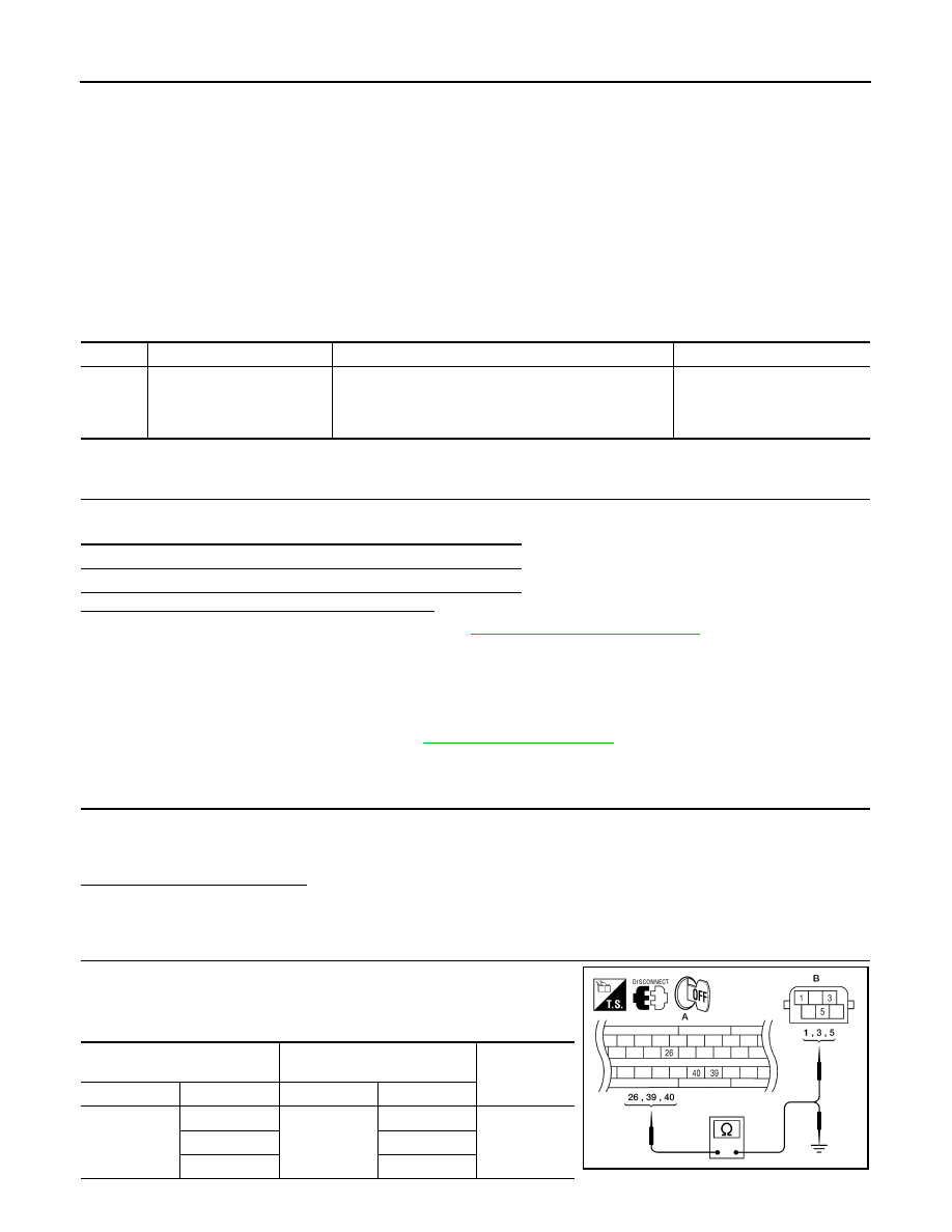
2.
DELTA STROKE SENSOR CIRCUIT INSPECTION
1. Measure the continuity between ABS actuator and electric unit
(control unit) connector E125 (A) and delta stroke sensor con-
nector E114 (B).
DTC
Display item
Malfunction detected condition
Possible cause
C1179
ABS DELTA S SEN NG
Delta stroke sensor is malfunctioning, or signal line of
delta stroke sensor is open or shorted.
• Harness or connector
• Delta stroke sensor
• ABS actuator and electric unit
(control unit)
Self-diagnosis results
ABS DELTA S SEN NG
ABS actuator and electric unit
(control unit)
Delta stroke sensor
Continuity
Connector
Terminal
Connector
Terminal
A: E125
26
B: E114
1
Yes
39
3
40
5
AWFIA0029ZZ